M 7-C / M 17-C / M 27-C Allgemeiner Teil / General Section
GRUNDIG Service 1 - 5
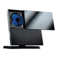
Fig. 6
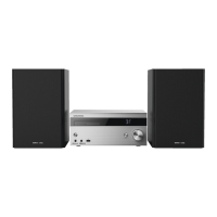
Fig. 7
G
G
J
J
J
J
H
K
L
L
L
M
M
N
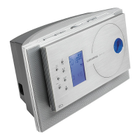
Fig. 8
P
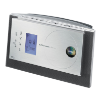
Fig. 9
R
O
Q
Fig. 10
6. Zerlegen der Front
- Lautstärkeknopf abziehen.
- 4 Schrauben G herausschrauben und die Tastenplatte H abneh-
men (Fig. 6).
- 12 Schrauben J herausschrauben und die Abdeckung K abneh-
men (Fig. 6).
- 5 Schrauben L herausschrauben und die Leiterplatte entnehmen
(Fig. 7).
7. NF-Platte ausbauen
- 2 Schrauben M (Fig. 8) herausschrauben.
- NF-Platte herausziehen, dabei Steckverbinder nach Bedarf öffen.
- Beim Wiedereinsetzen auf richtigen Sitz des Steckverbinders N
achten!
8. Ausbau der Netzanschlußplatte O (M 17-C, M 27-C)
- Schraube P (Fig. 9) und Schraube Q (Fig. 10) herausschrauben.
- Leiterplatte herausnehmen, dabei Steckverbinder R nach Bedarf
öffen.
6. Disassembling the Front
- Pull off the Volume Knob.
- Undo 4 screws G and remove the Key Board H (Fig. 6).
- Undo 12 screws J and remove the cover K (Fig. 6).
. Undo 5 screws L and remove the Board (Fig. 7).
7. Removing the AF Board
- Undo 2 screws M (Fig. 8).
- Remove AF Board, open connectors if necessary.
- When reassembling take care of correct position of the connector N.
8. Removing the Mains Connector Board O (M 17-C, M 27-C)
- Undo screw P (Fig. 9) and screw Q (Fig. 10).
- Remove Board, open connector R if necessary.
V
 Loading...