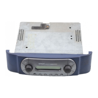
Allgemeiner Teil / General Section RCD 405
1 - 2 GRUNDIG Service
Es gelten die Vorschriften und Sicherheitshin-
weise gemäß dem Service Manual "Sicherheit",
Sach-Nummer 72010-800.00, sowie zusätzlich
die eventuell abweichenden, landesspezifischen
Vorschriften!
The regulations and safety instructions shall be
valid as provided by the "Safety" Service Manual,
part number 72010-800.00, as well as the
respective national deviations.
General Section
Test Equipment / Aids
Digital voltmeter, Sweep generator, Test generator, Stereo coder, AF
generator, Oscilloscope, AF voltmeter, Distortion meter
Please note the Grundig Catalog "Test and Measuring Equipment"
obtainable from:
GRUNDIG electronics GmbH
Würzburger Str. 150
D-90766 Fürth/Bay.
Tel. 0911/703-0
Telefax 0911/703-4479
Allgemeiner Teil
Meßgeräte / Meßmittel
Digitalvoltmeter, Wobbler, Meßsender, Stereokoder, Tongenerator,
Oszilloskop, NF-Voltmeter, Klirrfaktormeßgerät
Beachten Sie bitte das GRUNDIG Meßtechnik-Programm, das Sie unter
folgender Adresse erhalten:
GRUNDIG electronics GmbH
Würzburger Str. 150
D-90766 Fürth/Bay.
Tel. 0911/703-0
Telefax 0911/703-4479
Inhaltsverzeichnis
Seite
Allgemeiner Teil
Meßgeräte / Meßmittel ............................................................... 1 - 2
Technische Daten ...................................................................... 1 - 3
Bedienhinweise ............................ Service Manual RCD 400 S. 1 - 4
Ausbauhinweise ......................... Service Manual RCD 400 S. 1 - 13
Abgleichvorschriften
Tuner............................................ Service Manual RCD 400 S. 2 - 1
Platinenabbildungen und Schaltpläne
Display ........................................... Service Manual RCD 400 S. 3 - 1
IC-Block-Diagramme TDA1313T, SAA6579T ............................... 3 - 6
IC-Block-Diagramme TDA7294, LC7821 .................................... 3 - 16
Druckplattenabbildungen:
CD .......................................................................................... 3 - 1
Tuner ...................................................................................... 3 - 7
Netzteilplatte, Hauptplatte, Kopfhörerplatte, Display- und
Tastenplatten .......................................................................... 3 - 8
Klangreglerplatte, Lautstärkeplatte, Regulatorplatte ........... 3 - 10
Detailschaltpläne:
CD .......................................................................................... 3 - 2
Tuner ...................................................................................... 3 - 4
Hauptplatte, Kopfhörerplatte, Display- und Tastenplatte,
Netzteilplatte, Klangreglerplatte, Lautstärkeplatte,
Regulatorplatte ..................................................................... 3 - 11
Verdrahtungsplan........................................................................ 3 - 14
Ersatzteilliste und Explosionszeichnungen
Explosionszeichnung RCD 405 .................................................... 4 - 1
Explosionszeichnung CD-Laufwerk .............................................. 4 - 2
Ersatzteiliste.................................................................................. 4 - 3
Table of Contents
Page
General Section
Test Equipment / Aids ................................................................ 1 - 2
Specifications ............................................................................. 1 - 3
Operating Hints ............................ Service Manual RCD 400 S. 1 - 8
Disassembly Instructions ........... Service Manual RCD 400 S. 1 - 13
Adjustment Procedures
Tuner............................................ Service Manual RCD 400 S. 2 - 2
Layout of the PCBs and Circuit Diagrams
Display ........................................... Service Manual RCD 400 S. 3 - 1
IC Block Diagrams TDA1313T, SAA6579T .................................. 3 - 6
IC Block Diagrams TDA7294, LC7821 ....................................... 3 - 16
Layout of PCBs:
CD .......................................................................................... 3 - 1
Tuner ...................................................................................... 3 - 7
Mains Board, Main Board, Headphone Board, Display and
Key Boards ............................................................................. 3 - 8
Tone Control Board, Volume Board, Regulatot Board ......... 3 - 10
Circuit Diagrams:
CD .......................................................................................... 3 - 2
Tuner ...................................................................................... 3 - 4
Main Board, Headphone Board, Display and Key Board,
Mains Board, Volume Board, Regulator Board .................... 3 - 11
Wiring Diagram ........................................................................... 3 - 14
Spare Parts List and Exploded Views
Exploded View RCD 405 .............................................................. 4 - 1
Exploded View CD Drive Mechanism ........................................... 4 - 2
Spare Parts List ............................................................................ 4 - 3
D
GB
 Loading...