Do you have a question about the Grundig UMS 11 and is the answer not in the manual?
Lists measurement devices and tools required for service.
Provides specifications for amplifier, tuner, CD player, and cassette deck.
Steps to open the unit's casing and remove covers.
Procedure to remove the CD tray front panel.
Steps for removing the CD tray mechanism.
Procedure for setting the 24-hour clock time.
How to set the system to switch on automatically at a preset time.
Includes Mute function and Sleep timer settings.
Adjustment of the FM oscillator frequency and voltage.
Adjustment of the MW oscillator frequency and voltage.
Alignment of the FM IF stage for minimum distortion.
Adjustment of the AM IF stage.
Overall system block diagram showing functional connections.
Wiring diagram for the UMS 11 model.
Wiring diagram for the UMS 12 and UMS 12-S models.
Component layout and schematic for the control panel.
Circuit diagram and component layout for the power transformer board.
Schematic and component layout for the UMS 11 cassette deck.
Schematic and component layout for the UMS 12-S subwoofer.
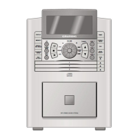
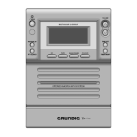
Diagram showing the exploded parts of the UMS 11 unit.
Diagram showing the exploded parts of the CD drive.
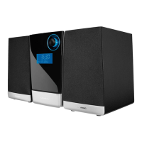
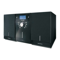
Diagram showing the exploded parts of the UMS 12 and UMS 12-S units.
Diagram showing the exploded parts of the UMS 12/12-S cassette drive.
List of spare parts for the UMS 12 model.
| Brand | Grundig |
|---|---|
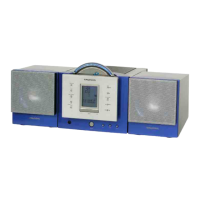
| Model | UMS 11 |
| Category | Stereo System |
| Language | English |