Allgemeiner Teil / General Section UMS 15
1 - 4 GRUNDIG Service
Ausbauhinweise
1. Öffnen des Gehäuses
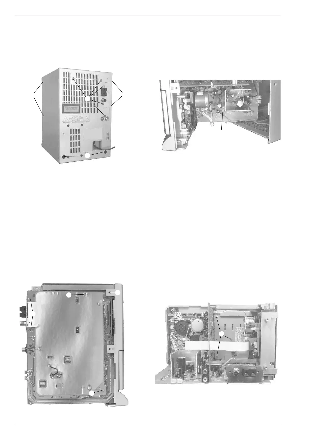
– 4 Schrauben A, 5 Schrauben B und 2 Schrauben C (Fig. 1)
herausdrehen.
– Rückwand ca.10cm nach hinten schieben, Steckverbinder CP204
(Fig. 2) abziehen und Rückwand abnehmen.
Fig. 1 Fig. 2
2. Hauptplatte
– 2 Schrauben D (Fig. 3) herausdrehen und Hauptplatte abnehmen.
– Bei Bedarf Steckverbindungen lösen.
Montagehinweis: Beim Einbau ist darauf zu achten, daß die Abschir-
mung wieder angebracht ist (Fig. 3).
3. Tunerplatte
– Hauptplatte ausbauen (Pkt. 2).
– 2 Schrauben auf der Tunerplatte herausdrehen.
– 2 Lötstellen E (Fig. 3) auflöten.
– Tunerplatte ablöten.
4. CD- und Bedienteil
– Hauptplatte ausbauen (Pkt. 2).
– Lautstärkeknopf abziehen.
– 3 Schrauben F (Fig. 4) herausdrehen.
– 2 Halter G (links/rechts, Fig. 3) ausrasten und CD- und Bedienteil
herausnehmen.
Fig. 3 Fig. 4
CP204
D
E
D
G
F
A
A
C
B
Disassembly Instructions
1. Opening the cover
– Undo 4 screws A, 5 screws B and 2 screws C (Fig. 1).
– Slide back the cover for about 10cm, pull off plug-in connector
CP204 (Fig, 2) and remove the cover.
2. Main Board
– Undo 2 screws D (Fig. 3) and remove the main board.
– Unplug the connectors if necessary.
Reassembly: When reassembling take care to refit the shielding
(Fig. 3).
3. Tuner Board
– Remove the main board (para 2).
– Undo 2 screws at the tuner board.
– Unsolder 2 solder tags E (Fig. 3).
– Unsolder the tuner board.
4. CD Part and Operating Board
– Remove the main board (para 2).
– Pull off the volume knob.
– Undo 3 screws F (Fig. 4).
– Disengage 2 holders G (left/right, Fig. 3) and remove the CD part
together with the operating board.




 To Next Page