EasyManua.ls Logo

Grundig Vision 4 32-4831 T User Manual

Grundig Vision 4 32-4831 T
64 pages
To Next Page IconTo Next Page
Page #1 background imageLoading...
Page #1 background image
TV Service Manual
Zusätzlich erforderliche Unterlagen für den Komplettservice
Additionally required Service Documents for the Complete Service
Service
Manual
Materialnummer / Part Number 720100538000
Änderungen vorbehalten / Subject to alteration
TCC 1108 HH • Prepared in Germany
http://www.grundig.com
Chassis SE
Toronto
26-7831 T GBH3126
Vision 6
42-6831 T GBH1342
37-6831 T GBH1337
32-6831 T GBH1332
32-6832 T ECO GBH1232
26-6831 T GBH1326
26-6832 T ECO GBH1226
26-6832 F T ECO GBH1227
Vision 4
42-4831 T GBH2442
37-4831 T GBH2437
32-4831 T GBH2432
32-4806 T GBH2332
26-4806 T GBH2326
Vision 3
37-3831 T GBH1537
32-3831 T GBH1532
32-3831 F T GBH1533
26-3831 T GBH1526
Sicherheit
Safety
Materialnr./Part No.
720108000001
NUR FÜR INTERNEN GEBRAUCH
FOR INTERNAL USE ONLY
Vorabversion
Preliminary Version
Question and Answer IconNeed help?

Do you have a question about the Grundig Vision 4 32-4831 T and is the answer not in the manual?

Grundig Vision 4 32-4831 T Specifications

General IconGeneral
BrandGrundig
ModelVision 4 32-4831 T
CategoryTV
LanguageEnglish

Summary

General Information and Specifications

General Notes and Safety

Basic operational, safety, and measurement guidelines.

Product and Display Variants

Details on different chassis and display configurations.

Technical Data Overview

Comprehensive specifications for various TV models.

Operating Hints and Controls

Guidance on using the TV and remote control.

Convenience Functions

Features like game mode, parental control, and system lock.

Service and Special Functions

Accessing service menus and special features.

PCB Layouts and Circuit Diagrams

Power Supply Circuit Diagrams

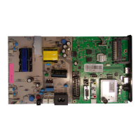
Schematics for the main power supply and panel power.

Input Connector Circuit Diagrams

Schematics for SCART, VGA, HDMI, and other inputs.

Tuner Circuit Diagrams

Schematics for the onboard TV tuner module.

COFDM Demodulator Circuit Diagram

Circuit diagram for the COFDM demodulator.

Scaler Circuit Diagram

Schematic for the video scaler and processing unit.

Audio Amplifier Circuit Diagram

Schematic for the audio amplification stage.

Chassis Board YCR190R-3 Component Layout

Component placement diagram for the main board.

Chassis Board YCR190R-4 Component Layout

Component placement diagram for the main board.

Power Supply Board Circuit Diagram

Schematic for the power supply board.

Keyboard and IR/LED Board Layouts

Component layouts for keyboards and IR/LED boards.

Related product manuals