3
Initial Setup
Restoring Factory Settings:
Wi-Smart
Step Description
1 Present Programming Card 2 Times
2 Present Any Card Once
Programming
Card x 2
AnyCard
x 1
Adding a Programming Card
Note: Add a progrmming card to the Door Control. The Door Control must
be disabled first if it has been enrolled onto a GSD Network Controller.
Follow the method below to add a programming card to the Door Control.
Adding a Programming Card
AnyCard
x 2
Step Description
1 Remove security caps and power down unit.
Power up unit and Present Any Card 2 times
2 immediately. This card is now the Programming
Card for the unit. Refit security caps
Factory Default PIN codes
The following PIN codes are the Factory Default Settings:
- The Default Engineer code is ‘6666’
- User PIN ‘1111’
Note: The User PIN ’1111’ is deactivated when the Door Control is enrolled
onto a GSD Network Controller.
14
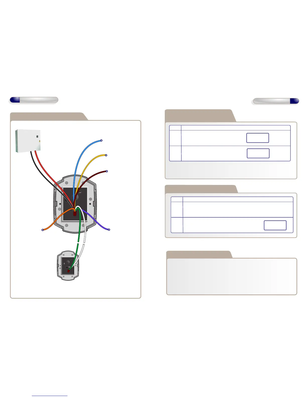
Wiring Diagrams
Wiring Diagram - Smart Slave
12V Linear
Power supply
Wi-Smart
(See manual for detailed
wiring diagram)
Data1/Clock OutputData0/Data Output
Tamper Alarm Output
12V DC
Only
0V
Buzzer Control Input
Green LED Input
Red LED Input
Card Present Output
Max Data Cable Length
- 100m Shielded Cable