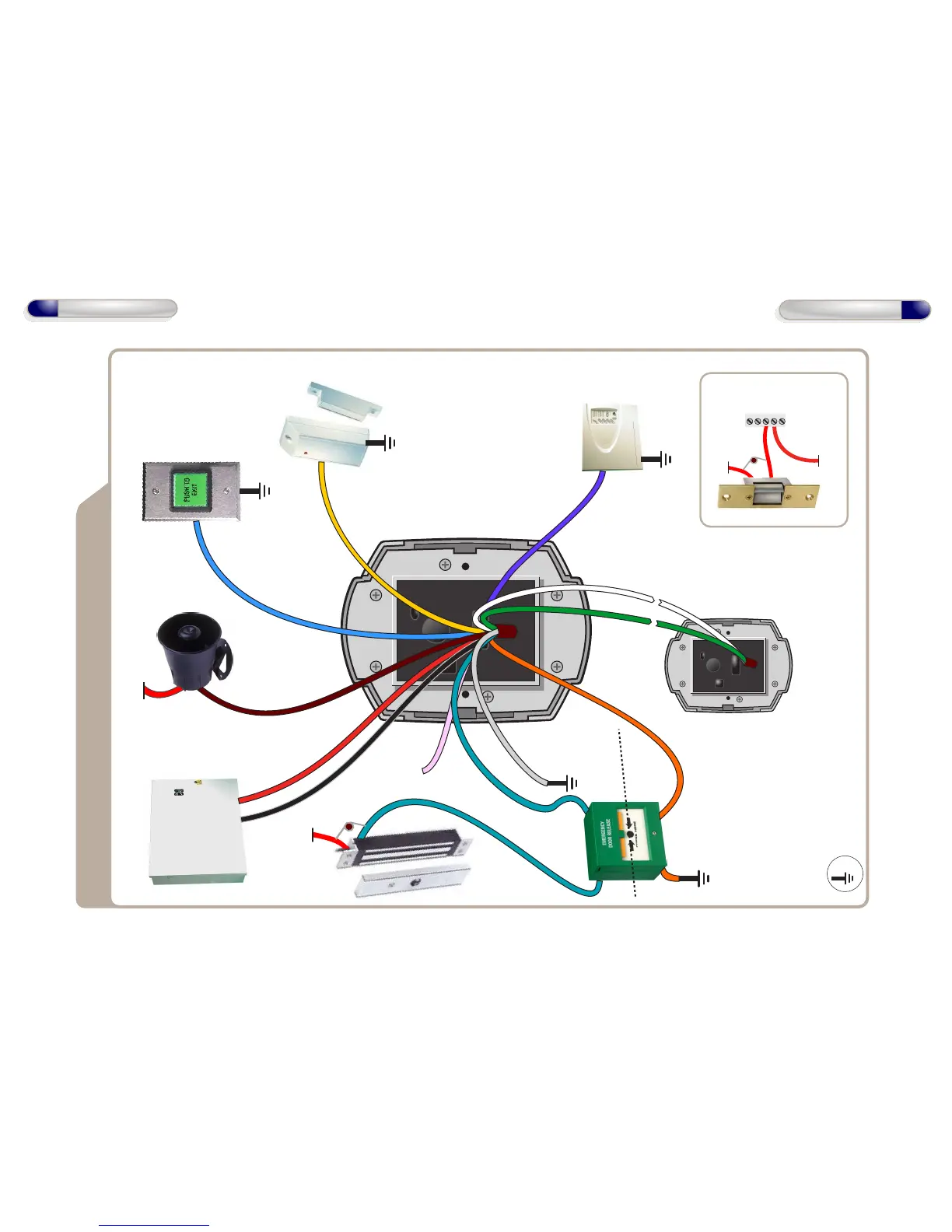
12V
Wiring Diagram with Slave Reader
12V Linear
Power supply
Door Exit Button
0V
Door
Contact
0V
Common the OV from the
Fire Alarm Panel and the OV
from the Door Control to
avoid any ground loop issues.
Note: Fire Alarm Override is
deactivated until the Door
Control joins a network.
Fire Alarm
Panel
0V
When the fire alarm
is activated (0V removed
from IP4) the door will
be opened
12V
Sounder
Smart Slave
(See page 14 for
wiring diagram)
12V
0V
NO
COM
NC
12 - 24 VAC
12 - 24 VAC
Wiring for StikeLock only using 12 - 24VAC supply
Note: All OV shown in the
diagram are connected to
OV of the Door Control.
0V
Dual-Pole
Ressetable
BreakGlass Unit
0V
Pole to cut
power to Lock
Pole for
Monitoring
Unit
NC
0V
COM
NO
IP5
Break Glass
OP1
Data1/Clock
IP3
Data0/Data
IP4
Fire Alarm
IP2
Door
Contact
IP1
Door Exit
Button
OP2
Alarm/Sounder
12V DC
Only
0V
Suggested Wiring
for BreakGlass
Unit above.
8
Wiring Diagrams
9
Wiring Diagrams
Max Data Cable Length
- 100m Shielded Cable
16V
Varistor
16V
Varistor