
D
Daniel HoffmanSep 14, 2025
What does 'ResLT ~ 1 !!' mean on my GSE Touch Panel?
- AAnthony SerranoSep 14, 2025
If the GSE Touch Panel displays 'ResLT ~ 1 !!', it means the number of divisions is less than one (see P110, P111).
What does 'ResLT ~ 1 !!' mean on my GSE Touch Panel?
If the GSE Touch Panel displays 'ResLT ~ 1 !!', it means the number of divisions is less than one (see P110, P111).
How to fix Code02 Under Load on GSE 355 I.S.?
If the GSE Touch Panel displays 'Code02 Under Load', you should check the load cell wiring and verify that the correct capacity selection is made at P110.
What does 'Bad ~ Code!' mean on my GSE 355 I.S.?
If the GSE Touch Panel displays 'Bad ~ Code!', it means that an incorrect access code was entered.
What does 'Out of ~ Range' mean on my GSE 355 I.S.?
If the GSE Touch Panel displays 'Out of ~ Range', it indicates that you attempted to enter a value beyond the allowable range.
What does 'ResLT ~ 100!' mean on my GSE 355 I.S.?
If the GSE Touch Panel displays 'ResLT ~ 100!', it means the number of divisions is less than 100 (see P110, P111).
What does 'Code 04' mean on GSE 355 I.S.?
If the GSE Touch Panel displays 'Code 04', the digits on the display have exceeded the six-digit display capacity.
What to do if my GSE 355 I.S. Touch Panel displays 'ReCal ~ ???'?
If the GSE Touch Panel displays 'ReCal ~ ???', repeat the calibration procedure for accuracy.
What does 'NoSpc ~ Free!' mean on my GSE Touch Panel?
If the GSE Touch Panel displays 'NoSpc ~ Free!', it means the current setup exceeds the setup RAM capacity.
What does 'Code 05' mean on GSE Touch Panel?
If the GSE Touch Panel displays 'Code 05', it means a zero attempt was made beyond that allowed by P118.
What does 'Need ~ Entry' mean on my GSE 355 I.S. Touch Panel?
If the GSE Touch Panel displays 'Need ~ Entry', it means that a numeric value was required before pressing the question mark button.
Defines hazardous locations, groups, duration, and temperature codes for safe operation.
Explains key terms related to intrinsically safe equipment and hazardous locations.
Describes the method for determining acceptable intrinsically safe apparatus combinations.
Lists electrical parameters for safe interconnection of devices.
Lists hazardous areas for which indicators and options are approved.
Details ATEX certification information for the equipment.
Outlines CSA certification for hazardous area classifications and parameters.
Lists built-in functions like check-weighing and parts counting enabled via setup.
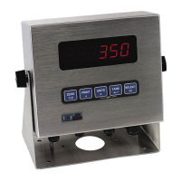
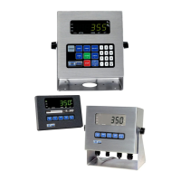
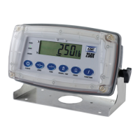
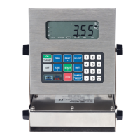
Highlights key physical and functional features like display types and communication ports.
Details performance, electrical, enclosure, display, communication, and keypad specs.
Describes LED and LCD display types, including annunciators and bargraphs.
Explains the functions of the 350 I.S. and 355 I.S. keypads in different modes.
Details interconnections between indicators and options using control drawings.
Provides measurements and diagrams for indicator installation.
Recommends cable types and explains sense jumper settings for load cells.
Covers RS-232, remote key, and remote display connection procedures.
Lists FM approved options for hazardous areas, emphasizing safe area installation.
Details the external battery module, its mounting, and operational hours.
Describes the external AC-DC power supply and its powering capabilities.
Explains fiber-optic transceivers for setpoint and analog output interfacing.
Details components for installing options in a safe area hub.
Explains installing setpoint option boards in the Safe Area Hub.
Describes installing the analog output module for interfacing.
Provides keystroke sequences to access setup for configuration.
Guides on selecting, changing, saving parameters, including factory defaults.
Describes selecting values from predefined lists.
Explains entering numerical values directly.
Covers Preset and Custom Transmit selections for data transmission.
Explains how to enable and use the parts counting feature and sampling methods.
Introduces pre-programmed setpoint applications and their general activation methods.
Covers Fill, Batch, Discharge, Both, Absolute Check-Weighing, Independent Setpoint, Target Deviation.
Explains how setpoints are activated through Tare, Remote Key, Auto, or Start key functions.
Describes pre-act functions used to prevent overfilling and compensate for system variables.
Explains how the learn feature automatically adjusts cutoff values based on previous fills.
Details how to pause setpoint operations for mid-cycle adjustments or breaks.
Guides on modifying target values and subsets directly from the weigh mode.
Guides on setting and accessing the unit's time and date features.
Explains how to assign functions to remote keys.
Provides instructions for updating the indicator's firmware using a computer.
Details the setup and calibration procedures for the analog output module.
Covers configuring master and slave indicators for remote display functionality.
Lists parameters to set on the master indicator for remote display.
Guides on configuring the slave indicator for remote display.
Explains how to access calibration from setup mode.
Describes a quick calibration method that bypasses the main setup mode.
Covers the general process of calibration, starting with zero and span references.
Details five methods for establishing a zero (no-load) reference for calibration.
Explains the common zeroing procedure for first-time calibration or recalibration.
Describes recalibrating using an existing test load, beneficial for high-capacity applications.
Explains calibrating without removing current gross weight, useful for tank weighing.
Details establishing a new zero without affecting span, useful for correcting dead load changes.
Explains when and how to reset calibration to factory defaults for amplifier adjustment.
Describes using multi-point linearization to improve accuracy for signals with stability issues.
Steps for establishing the first zero point in multi-point linearization.
Procedure to reset calibration points during multi-point linearization.
How to view calibration weights and calculated factors using specific parameters.
Guides on establishing a span (test load) reference after setting the zero.
Details how to save acquired calibration information or exit without saving.
Standards for weights and measures in the US, referencing Handbook 44.
International metrology regulations and their compliance requirements.
Parameters to consider for individual applications regarding legal-for-trade compliance.
Provisions for sealing indicators and using audit trail counters to prevent tampering.
Method for securing the indicator using a lead-wire seal.
Explains parameters that track changes to settings and calibration.
Comprehensive list of error codes categorized into Operational, Setup Mode, Hardware, Calibration, and Communication.
Errors related to load conditions, function status, and display limits.
Errors encountered during setup mode, such as incorrect codes or invalid entries.
Errors related to internal hardware components like FRAM or A/D chips.
Errors occurring during the calibration process, such as incorrect span weights.
Errors related to data transmission and port settings mismatches.
How to view setup parameter selections without allowing modifications.
Accessing parameters for viewing system status and information.
Procedures for removing and installing the main board.
Procedures for removing and replacing the keypad unit.
Procedures for removing and replacing the display unit.
Diagrams for connecting peripherals in hazardous and safe areas.
| Brand | GSE |
|---|---|
| Model | 355 I.S. |
| Category | Touch Panel |
| Language | English |