
L
Lisa BurkeSep 23, 2025
What does error code '(E0300)' mean on GSE Touch Panel?
- CchristineperkinsSep 23, 2025
If your GSE Touch Panel displays '(E0300)', enter setup and calibrate the device.
What does error code '(E0300)' mean on GSE Touch Panel?
If your GSE Touch Panel displays '(E0300)', enter setup and calibrate the device.
Why does my GSE Touch Panel show a '(ZERO) (ERROR)' message?
If the GSE Touch Panel displays a '(ZERO) (ERROR)' message, it means the zero key operation is limited by the setup during installation, and the indicator cannot be zeroed at the current weight. To resolve this, increase the Zero Range (Z.RANGE) or use the [TARE] key instead.
What causes the '(LO) (SPAN)' error on my GSE Touch Panel?
If your GSE Touch Panel displays '(LO) (SPAN)', it means an incorrect span weight was entered (it must be between zero and full scale), the scale wiring is incorrect, the load cell capacity is wrong (too large), or there's no calibration weight added to the scale. Check these possible causes.
What does '(SPAN) (HI)' mean on my GSE Touch Panel?
If the GSE Touch Panel displays '(SPAN) (HI)', it indicates that an incorrect span weight was entered (must be between zero and full scale), the scale wiring is incorrect, or the load cell capacity is too small for the application. Investigate these potential issues.
How to fix the '(U - - - - -)' error on GSE Touch Panel?
If your GSE Touch Panel displays a '(U - - - - -)' error, increase the weight or decrease the minimum allowable weight reading.
What does error code '(E0200)' mean on GSE Touch Panel?
If your GSE Touch Panel displays '(E0200)', recalibrate the device.
What does error code '(E0020)' mean on GSE Touch Panel?
If the GSE Touch Panel displays '(E0020)', enter the correct graduation size at BUILD:DP and BUILD:RES.
What does error code '(E0100)' mean on GSE Touch Panel?
If your GSE Touch Panel displays '(E0100)', enter setup.
What does '(RES) (LO)' mean on the GSE Touch Panel?
If the GSE Touch Panel displays '(RES) (LO)', check the resolution (count-by) and capacity settings.
What to do if my GSE Touch Panel displays '(ENTRY) (DENIED)'?
If the GSE Touch Panel displays '(ENTRY) (DENIED)', access the Full Setup to edit the parameter.
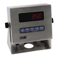
Description of the standard ABS plastic version of the Model 250 indicator, including its mounting options and power source.
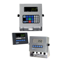
Details on the Model 250SS Panel Mount, featuring a stainless steel face and membrane keypad.
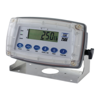
Information about the Model 250X, designed for washdown applications with an IP69K enclosure.
Details on making cable connections to the rear of the indicator models.
Explains how to connect load cells using either 4-wire or 6-wire configurations.
Diagrams and instructions for connecting the indicator to a computer via RS-232 serial ports.
Describes how to access Full Setup and Safe Setup modes, including access code protection.
Configuration settings within the BUILD group for application suitability.
Procedures for performing zero and span calibration using physical test weights.
Explains operation modes (Industrial, NTEP, OIML) and trade regulation compliance.
Details on configuring the indicator to comply with National Type Evaluation Program standards.
Information on configuring the indicator to meet International Organization of Legal Metrology standards.
Instructions for using the GSE View software for parameter setup and communication.
Lists and explains various error messages displayed by the indicator.
Describes status messages and errors that may occur during normal weighing operation.
Details status messages and errors encountered during setup and calibration processes.
Explains specific error codes for faults or out-of-tolerance conditions.
| Brand | GSE |
|---|---|
| Model | 250 |
| Category | Touch Panel |
| Language | English |