Page 20 250 Technical Reference
C
C
O
O
N
N
N
N
E
E
C
C
T
T
I
I
N
N
G
G
S
S
H
H
I
I
E
E
L
L
D
D
S
S
To obtain full EMC or for RFI immunity, cable shields MUST be connected to the ground lug on
the rear of the indicator.
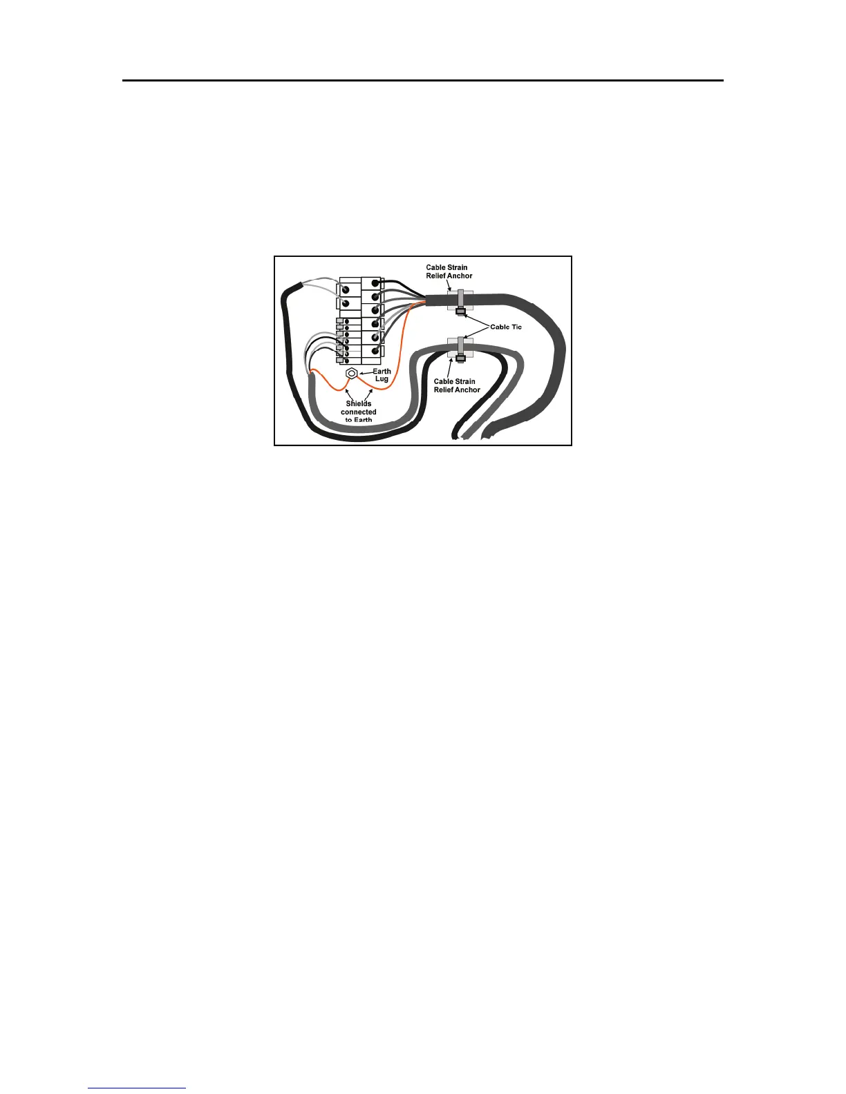
Figure 5 illustrates an example of possible connections. Also shown are the connecting cables
restrained using cable ties fastened around the cable strain relief anchors.
Figure 5: Cable Shield Connection
Care should be taken when connecting shields to maximize EMC or RFI immunity and minimize
ground loops and cross-talk (interference) between indicators.
For full EMC or for RFI immunity, termination of the cable shields at the ground (earth) lug is very
important. The ground lug of the indicator must be separately connected to ground potential via a
reliable link.
The Model 250 should only be connected to ground via a single reliable link to avoid ground
loops.
Where each indicator is separately grounded, interconnecting cable shields should be connected
at one end only.


 To Next Page