4. Test Firing
18 PNEG-1456 1 and 2 Fan Vision Series Portable Dryers
Burner Safety
To check the burner safety function, first make sure the main gas valve is OFF. Turn the Fan switch ON and
allow the fan to start. Turn the Heater switch ON for that fan. The dryer will shutdown after 20 seconds. The
safety message, “Ignition Failure Fan #” will appear. Reset the dryer and repeat for the other fan/heater(s).
Burner Test Fire
To perform this test, the dryer must be full of grain. If the dryer is empty, the air switch must be disabled.
To disable, touch the Setup button at the bottom of the Default Operation Screen. When the Setup Screen
appears, touch the Diagnostics button to display the System Diagnostics. To disable the air switch, select
the Disable Testing button in the air switch box of the System Diagnostics Screen. The Vision computer
will then display a prompt asking if you wish to disable the air switch. Choose YES to continue. Once the
air switches are disabled, the Fan switches on the switch panel will illuminate and the fan/heaters on the
display animation will change to blue, indicating that “airflow” is simulated.
There is only a 5 minutes period after the dryer is turned on that the air switches can be disabled. After
5 minutes, the air switches cannot be disabled and any air switches that are disabled will return to the
enabled state causing an airflow shutdown if the dryer is empty. To restart the 5 minutes test period, the
dryer must be shutdown and restarted. The 5 minutes test period starts when the Control Power switch is
turned ON.
Test fire each burner by starting the fan. Turn on the fuel supply, then turn the Burner switch to ON. The
burner should ignite after a short purge delay of approximately 10 seconds. Gas pressure should be shown
on the gauge. At this time adjust the plenum setpoint to 200°F (93°C), causing the burner to operate on
High-Fire. Observe the gas pressure on the gauge and lower the plenum setpoint until it causes the burner
to cycle into Low-Fire. When the plenum temperature setpoint is met, the gas pressure should show a
noticeable drop, indicating that the cycle solenoid is closed and the burner is being supplied with less gas
through the cycle solenoid bypass port. At this time set the High-Fire and Low-Fire pressure settings. Use
the pressure regulator (for LP models) or the supply line ball valve (for natural gas models) for High-Fire
and the adjustment screw on the cycle solenoid for Low-Fire. The computer should cycle the burners
between high and low, approximately 1 to 3 times per minute.
Use only the amount of pressure required to obtain the desired temperature.
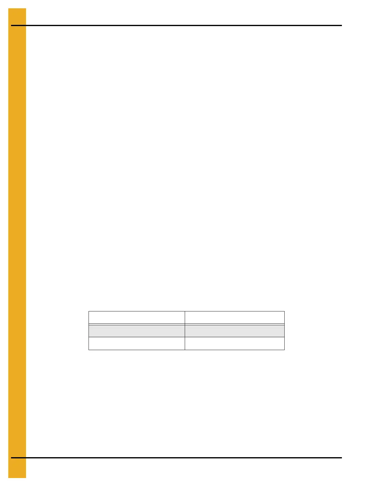
Approximate settings are shown below:
If the burner remains on High-Fire and does not cycle, increase the regulator setting on the propane
models, or the supply valve on the natural gas models, in order to reach the plenum setpoint. If the burner
remains in Low-Fire and does not cycle, slightly decrease gas pressure with the Low-Fire adjustment
screw on the cycle solenoid. If the gas pressure is decreased too much, a popping or fluttering sound will
be heard. This popping and fluttering should not be allowed to continue or damage to the burner will occur.
Be sure to adjust the low pressure needle valve anytime the high pressure regulator is adjusted. Repeat
the test for each fan/heater unit.
LP Gas Natural Gas
High-Fire 6-15 PSI (41-102 kPa) High-Fire 6-10 PSI (41-69 kPa)
Low-Fire 2-6 PSI (14-41 kPa) Low-Fire 1-3 PSI (7-20 kPa)
 Loading...