3. Installation
12 PNEG-1717 CE Approved GSI/FFI Portable Dryer Manual
Natural Gas (N)
Gas Volume and Pressure
Natural gas supply should offer:
1. 49 MJ/m3 calorific value.
2. 650 mBar supply pressure. (Lower pressure may inhibit dryer performance.)
3. Gas pipework and controls from the supply to the dryer must be installed by the gas supplier in
accordance with local directives, laws, codes and regulations.
Check the supply capacity against dryer requirements. (See heater rating plates for details.)
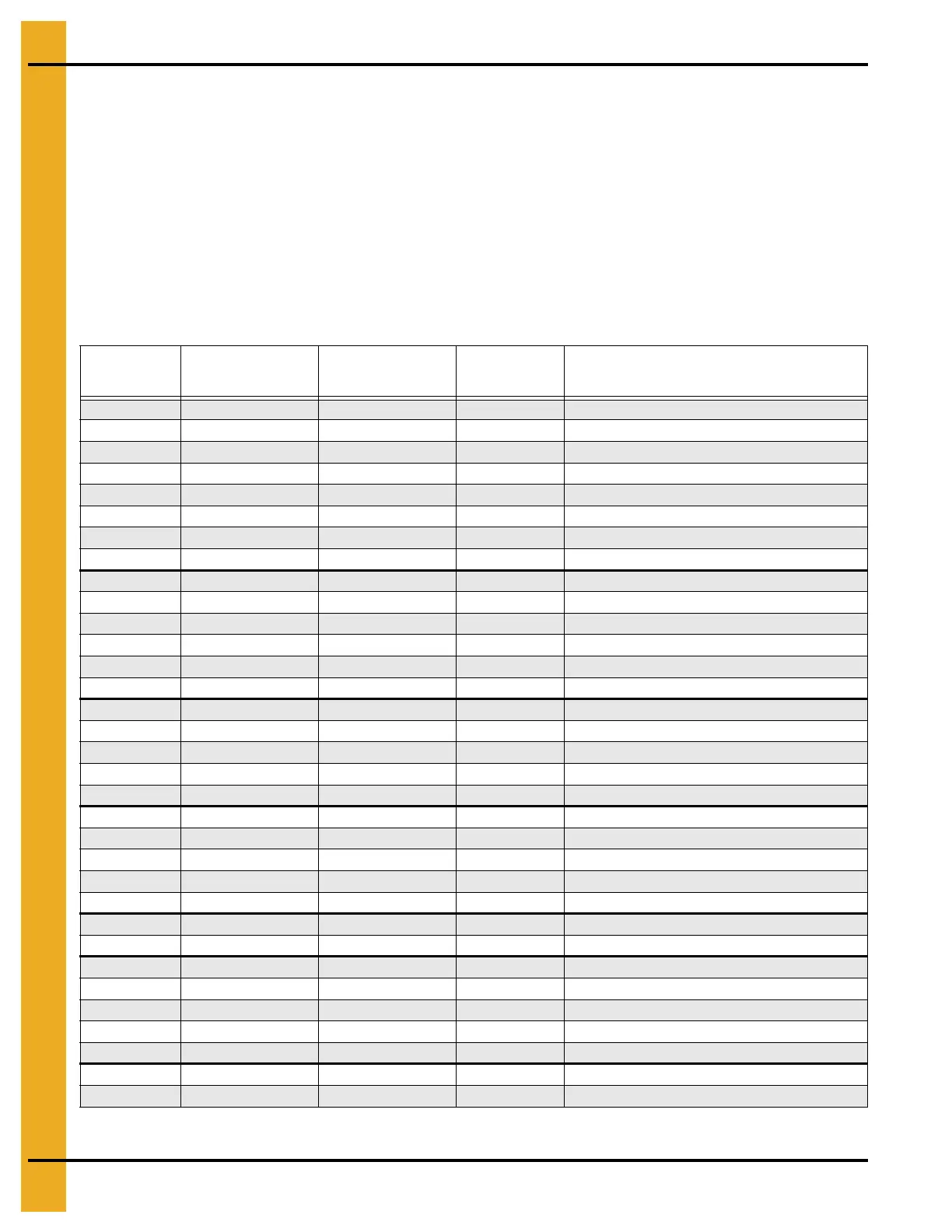
Fuel System Specifications and Recommendations (NG) Natural Gas
Dryer
Model #
Maximum Heat
Capacity kW
Maximum Fuel Flow
m3/h
Fuel Line Size
mm *
Heater Orifice Diameter mm **
(U = Upper, L = Lower, Heater Position)
(T = Top, M = Middle, B = Base Dryer Module)
1108/190 880 82 32 9.7
1112/270 1320 123 38 11.9
1114/320 1685 157 38 13.3
1116/370 1685 157 38 13.2
1118/400 2052 188 50 14.1
1120/460 2200 206 50 14.9
1122/511 2491 233 50 15.3
1126/601 2785 261 50 16.5
1214/2120 1700 158 38 (U)10.5 (L)8.1
1216 1993 186 50 (U)12.9 (L)8.1
1218/2125 1993 186 50 (U)12.9 (L)8.1
1220/2130 2565 239 50 (U)13.3 (L)8.1
1222 2931 273 50 (U)13.3 (L)8.1
1226/2140 3078 287 50 (U)14.1 (L)8.1
1214S/2141 2052 191 38 (U+L) 10.5
1218S/2181 2638 246 38 (U+L) 12.9
1220S/500H 3371 314 50 (U+L) 13.3
1222S/2221 4104 316 50 (U+L) 14.1
1226S/650M 4397 410 50 (U+L) 14.9
2314/3142 3445 321 50 T 13.3 B (U+L) 9.7
2318/3182 4104 316 50 T 14.1 B (U+L) 10.5
2320/3202 4837 451 80 T 14.9 B (U+L) 12.9
2322/3222 5130 478 80 T 15.3 B (U+L) 12.9
2326/3262 7183 669 80 T 16.6 B (U+L) 13.7
2420/1000H 5277 492 80 (T+B, U+L) 12.9
2426/1300M 7622 710 80 (T+B, U+L) -13.7
3414/4143 5130 478 80 T 13.3 M 13.3 B (U+L) 9.7
3418/4183 6156 574 80 T 14.1 M 14.1 B (U+L) 10.5
3420/4203 7036 656 80 T 14.9 M 14.9 B (U+L) 12.9
3422/4223 7622 710 80 T 15.3 M 15.3 B (U+L) 12.9
3426/4263 9381 874 80 T 16.6 M 16.6 B (U+L) 13.7
3620/1500H 7915 738 80 (T+M+B, U+L) 12.9
3626/2000M 11433 1065 80 (T+<M+B, U+L) 13.7
* Maximum line size for a 100' distance. ** Maximum burner pressure 450 mBar.
 Loading...