3. Installation
PNEG-900 Series 2000 Autoflow Fan/Heater and Control Installation Instructions 15
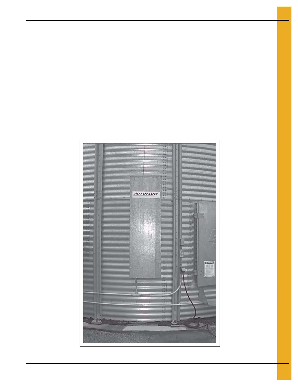
Actuator Control Box Mounting
1. Mark the third sidewall ring from the ground to indicate the cable path if dump chutes and cable are
already installed.
2. Make sure that all dump chutes and chains are EVENLY adjusted so that when one chute is level the
others are level as well.
3. Keep in mind that wire will be used to interconnect the actuator control box with the Autoflow control
box; and, that a 110V power supply will need to run from the entrance panel to the actuator control
box to power the 24V DC battery charger.
4. Use the pattern in Figure 3G on Page 16 to drill holes for the actuator control box.
5. If the horizontal seam bolts are within 1" horizontally of the hole pattern shown, existing holes may
be used to attach the actuator.
6. Use four (4) 5/16" x 1-1/4" bin bolts and washers with bolt heads to the inside of the bin.
7. Do not attach the dump chute cable to the actuator at this time. The cable should not be installed until
after the actuator unit is completely wired and tested.
Figure 3F Actuator Control Box Mounted to Bin
 Loading...


