4. Electrical Power Supply
PNEG-900 Series 2000 Autoflow Fan/Heater and Control Installation Instructions 41
Autoflow to Master Fan/Heater Unit Interconnect
The master fan/heater unit is the only fan and heater in a single fan unit. In two (2) fan units it is the
fan/heater with the air switch, plenum temperature sensor and grain temperature sensor connected to it.
DO NOT run the control wires for the master fan/heater in the same conduit as the power wires for the fan
motor. To wire the master fan/heater unit to the Autoflow control box do the following.
NOTE: Do NOT use solid wire for interconnections.
NOTE: A shielded 16 gauge cable is recommended for use on the network connection. The network
wires for this configuration are attached to terminal #4 and terminal #5. Ground each end of the
shielded cable to the housing. A shielded 16 gauge 2 wire cable can be purchased from GSI.
Part #WR-16/2S.
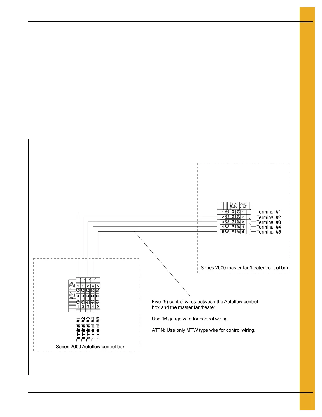
1. Run five (5) control wires from the Autoflow control box to the master fan/heater unit.
2. Connect the wires as shown in Figure 4E.
Figure 4E Master Fan and Heater Dip Switch Setting: #1 - “OFF”/All Others - “ON”
 Loading...


