4. Electrical Power Supply
38 PNEG-900 Series 2000 Autoflow Fan/Heater and Control Installation Instructions
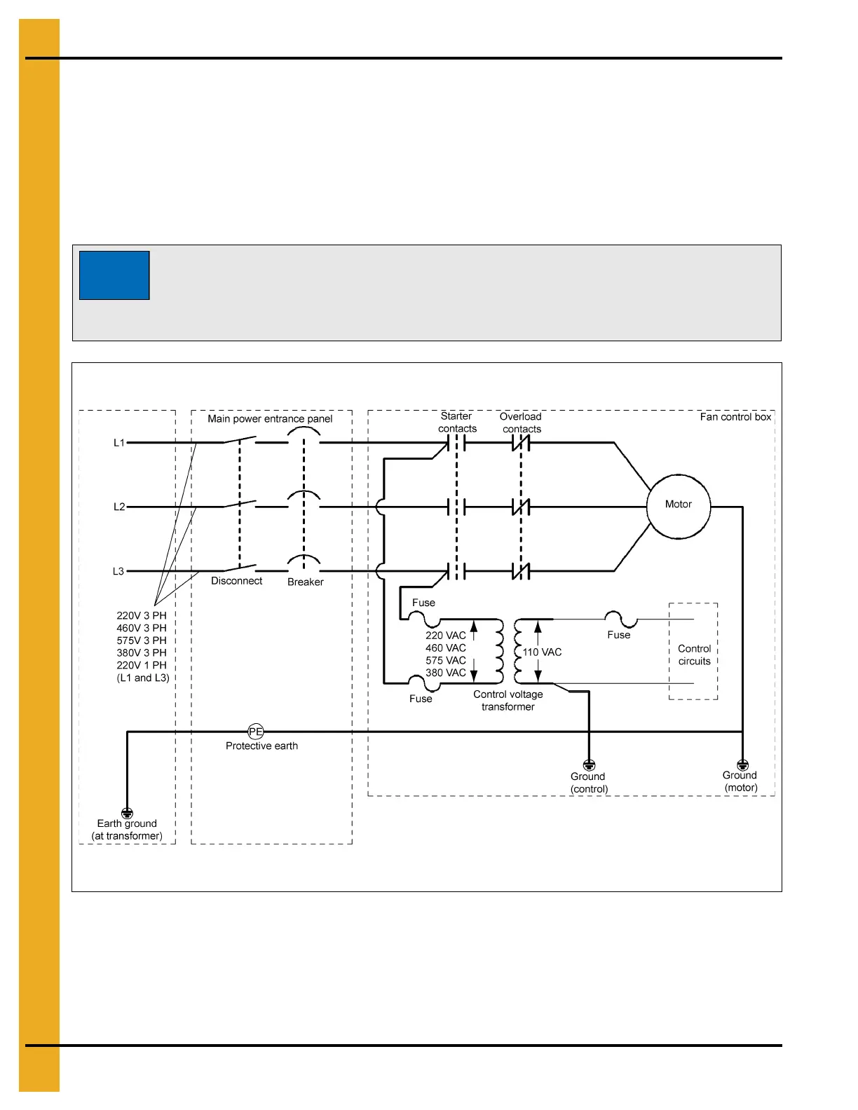
Power/Motor Wiring
The Figure 4C details the configuration for correct main power installation. Use the diagram in conjunction
with the electrical load information and wire size information provided. The diagram details the correct
main power installation for 220V 1 PH, 230V 3 PH, 460V 3 PH, 575V 3 PH and 380V 3 PH 50 Hz
power supplies.
On all 3 phase systems put the leg with the highest potential difference between that leg and ground (wild
or high voltage leg) on the center terminal (L2) at the motor starter.
Figure 4C Main Power Schematic
Standard electrical safety procedures should be used. (Refer to the National
Electrical Code Standard Handbook by the National Fire Protection Association.)
A qualified electrician should make all electrical wiring installations. Follow all
local or national electrical safety standards and ordinances when installing
the equipment.
 Loading...


