EasyManua.ls Logo

GST GST-AS-200 - User Manual

GST GST-AS-200
2 pages
Print Icon
To Next Page IconTo Next Page
Loading...
30306435 Issue 1.02
Features
Aesthetical appearance and good protection
against interference.
Simple installation and operation.
Description
GST-AS-200, GST-AS-300 Zener Safety Barrierthe
barrieris associated with intrinsically safe products. It
provides protection by limiting the energy into
explosive environment. Used together with
explosive-proof detectors and manual call points from
GST, the barrier is suitable for protecting the automatic
control process in modern industries such as
petroleum industry, chemical industry, pharmaceutical
industry, and ship yards.
The protection of the barrier is actually the limiting of
energy. In an explosion-proof system, the barriers
ensures the energy output always be controlled under
a safe value (that will not ignite the explosive gas
mixture classified and grouped according to relative
standards) in case of any kind of fault condition.
The barrier restricts the voltage through a voltage
stabilizing diode. When the input voltage rises sharply,
the diode will be turned on and control the output
voltage below the upper limit. The current of the diode
will rise sharply when turned on. If the input voltage is
too high or high voltage lasts too long, the fuse
connected in the circuit in series will be blown to cut off
the high voltage to the devices in field. When the load
in field is in short circuit, the current-limiting resistor in
the circuit of the barrier will limit the output current
below its upper limit.
Ex Area
Safety Area
Connection & Cabling
Terminals are shown below.
Description:
No.
Terminals
GST-AS-200
GST-AS-300
1
Non-intrinsically
safe side
Positive
Polarity-
insensitive
2
Non-intrinsically
safe side
Negative
(internal
earth)
3
Intrinsically
safe side
Positive
Polarity-
insensitive
4
Intrinsically
safe side
Negative
(internal
earth)
Installation
The barrier should be installed by copper busbar.
Warning: Power must be disconnected from the
loop before installation.
GST-AS-200/300 Zener Safety Barrier
Ssfety Area
Question and Answer IconNeed help?

Do you have a question about the GST GST-AS-200 and is the answer not in the manual?

Summary

Product Description and Function

Product Overview and Application

Details the GST-AS-200/300 Zener Safety Barrier's role in protecting automated control processes in hazardous industries.

Protection Mechanism

Explains how the barrier limits energy to a safe value, preventing ignition of explosive gas mixtures under fault conditions.

Circuit Operation Details

Describes the barrier's voltage stabilization, current limiting resistor, and fuse protection against overvoltage and short circuits.

Connection and Installation

Connection & Cabling

Illustrates terminal connections for the safety barrier, specifying pairings for different safety sides.

Installation Guidelines

Instructs on installing the barrier using a copper busbar and emphasizes disconnecting power before installation.

Product Specifications and Safety

Application Diagram

Visual representation of the barrier's application, showing connections between safe and hazardous areas.

Technical Specifications

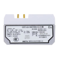
Lists key electrical and environmental parameters of the safety barrier, including voltage, current, and temperature ratings.

Safety Cautions

Provides critical safety advice for installation, testing, and cabling to ensure proper barrier function and user safety.

Limited Warranty Information

Outlines the terms and conditions of the product warranty, including coverage and exclusions for defects and misuse.

Overview

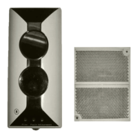
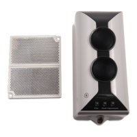
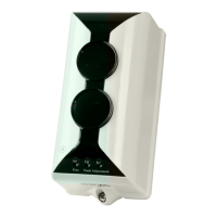
The GST-AS-200/300 Zener Safety Barrier is a device designed to provide protection for intrinsically safe products by limiting energy into explosive environments. It is specifically intended for use with explosive-proof detectors and manual call points from GST, making it suitable for automatic control processes in various industries such as petroleum, chemical, pharmaceutical, and shipbuilding.

Function Description

The primary function of the barrier is to limit energy. In an explosion-proof system, the barrier ensures that the energy output is always controlled below a safe value. This prevents the ignition of explosive gas mixtures, even under fault conditions.

The barrier achieves this by restricting voltage through a voltage-stabilizing diode. When the input voltage increases sharply, the diode activates, controlling the output voltage below its upper limit. If the input voltage is excessively high or prolonged, a series-connected fuse in the circuit will blow, cutting off the high voltage to the field devices. In the event of a short circuit in the field load, a current-limiting resistor within the barrier's circuit restricts the output current below its upper limit.

Important Technical Specifications

The GST-AS-200/300 Zener Safety Barrier has the following key specifications:

  • Operating Voltage: 24V
  • Maximum Voltage Allowed (Um): 250VAC/DC
  • Maximum Output Voltage (Uo): 28V
  • Maximum Output Current (Io): 93mA
  • Maximum External Capacitance (Co): 0.083uF
  • Maximum External Inductance (Lo): 4mH
  • Ambient Temperature: -20℃ to +40℃
  • Relative Humidity: <95%, non-condensing
  • Dimensions: 96.9mm × 20.9mm × 58.4mm
  • Weight: Approximately 0.12kg

Model-Specific Parameters:

Model Voltage (V) End Resistor (Ω) Basic Circuit (Non-Intrinsically Safe) Basic Circuit (Intrinsically Safe)
GST-AS-200 24 330 0 -
GST-AS-300 24 320 320 -

Usage Features

The barrier offers several user-friendly features:

  • Aesthetical Appearance: Designed with a pleasing aesthetic.
  • Interference Protection: Provides good protection against external interference.
  • Simple Installation and Operation: Designed for ease of setup and use.
  • Terminal Connections:
    • Non-intrinsically safe side: Positive (Terminal 30) and Negative (Terminal 40, internal earth).
    • Intrinsically safe side: Positive (Polarity-insensitive) and Negative (Internal earth, Polarity-insensitive).
  • Installation: The barrier should be installed using a copper busbar.

Maintenance Features

Proper installation and maintenance are crucial for the barrier's performance and safety:

  • Installation Location: Must be installed in a safe area.
  • Cabling: Cables from both the intrinsically safe and non-intrinsically safe sides must be connected correctly, paying attention to the lead polarity of the GST-AS-200 barrier.
  • Earthing: The barrier must be earthed, with the resistance at the earth electrode not exceeding 1Ω.
  • Insulation Testing: It is strictly prohibited to test the insulation between terminals directly using a megohmmeter. The barrier must be disconnected before any system connection testing.
  • Compatibility: Cables, equivalent capacitance, and inductance distribution of connected devices on the non-intrinsically safe side must meet the safety requirements of the barrier.
  • Manual Compliance: Installation, operation, and maintenance must comply with this manual.
  • Power Disconnection: Power must be disconnected from the loop before installation.

Limited Warranty

GST provides a warranty for the product, covering defects in design, materials, and workmanship during the warranty period. This warranty does not cover products that have been improperly installed or used in ways not in accordance with the provided instructions. The company emphasizes that no agent, distributor, or employee is authorized to amend the terms of this warranty. For products not covered by the warranty, customers are advised to contact their local distributor.

GST GST-AS-200 Specifications

General IconGeneral
BrandGST
ModelGST-AS-200
CategorySecurity Sensors
LanguageEnglish

Related product manuals