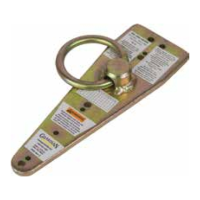
The G-Bolt, Part #: 00235, is a Type A anchorage connector designed for fall protection applications. It is compliant with OSHA 1926 Subpart M, OSHA 1910, ANSI Z359.18-2017, and ANSI A10.32-2012 standards. This device is intended to be used as part of a personal fall arrest system (PFAS), restraint system, or rescue/confined space system.
Function Description:
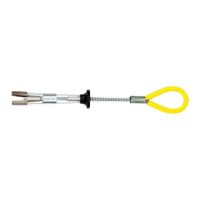
The G-Bolt serves as a temporary or permanent anchor point in concrete structures for fall protection. It is designed to be inserted into a pre-drilled hole in concrete, providing a secure attachment point for fall protection equipment. The device features a trigger and spring mechanism that allows for easy installation and removal. Once installed, it provides a connection point for various fall protection connectors, such as snap hooks or carabiners, to secure a worker. The G-Bolt is suitable for use in horizontal lifeline (HLL) applications, provided all installation requirements are met.
Important Technical Specifications:
- Capacity: The G-Bolt has a worker weight capacity range of 130-420 lbs, including all clothing, tools, and equipment.
- Minimum Breaking Strength (MBS): It boasts a 5,000 lb. MBS, ensuring robust strength for fall arrest scenarios.
- Minimum Permitted Service Temperature: The device is designed to operate effectively in temperatures as low as -30° F.
- Materials: The G-Bolt is constructed from a combination of durable materials, including aluminum, polyurethane, aircraft cable, stainless steel, zinc-plated steel, and zinc-plated copper.
- Dimensions: The overall length of the G-Bolt is approximately 11.5 inches. The connection point loop has a diameter of approximately 2 inches.
- Concrete Requirements for Installation:
- If the installation location is between 6" and 12" from any edge/corner, the concrete must be 12" thick and have a minimum compressive strength of 3,000 psi.
- If the installation location is greater than 12" from any edge/corner, the concrete must be 6" thick and have a minimum compressive strength of 3,000 psi.
- The G-Bolt must not be installed if the location is less than 6" from any edge/corner.
- It is exclusively for use in concrete substrates; installation into other substrates is not permitted.
- Hole Specifications for Installation: A 3/4" (20mm) diameter hole, at least 3.5" (89mm) deep, is required. The hole must be straight, perpendicular to the substrate, and have a uniform diameter without peaks or valleys on the inner wall.
- Maximum Connections: Only one attachment per connection point is permitted.
Usage Features:
- Personal Fall Arrest: Supports a MAXIMUM of 1 personal fall arrest system. The structure must withstand loads of at least 5,000 lbs. Maximum free fall is 6', or up to 12' if used with explicitly certified equipment. Applicable D-ring: Dorsal.
- Restraint: Prevents workers from reaching fall hazards. Structure must withstand loads of at least 1,000 lbs. No free fall is permitted. Usable on surfaces with slopes up to 4/12 (vertical/horizontal). Applicable D-rings: Dorsal, Chest, Side, Shoulder.
- Rescue/Confined Space: Functions to safely recover workers. Structure must withstand loads of at least 3,000 lbs. No free fall is permitted. Applicable D-rings: Dorsal, Chest, Shoulder.
- Compatibility: All connections must be self-closing and self-locking, withstand minimum loads of 3,600 lbs, and be deemed compatible by a Competent Person to eliminate roll-out risk. Examples of incompatible connections include two or more snap hooks/carabiners connected to each other, two connectors to the same D-ring, direct connection to webbing, load on the gate, or direct connection to a horizontal lifeline.
- Installation Process:
- Drill a 3/4" (20mm) diameter hole at least 3.5" (89mm) deep, ensuring it is straight and perpendicular to the substrate.
- Clean the hole with compressed air.
- Compress the trigger and spring by placing the thumb inside the anchor loop and fingers around the trigger.
- Insert the G-Bolt a minimum of 3" (76mm) deep into the hole and release the trigger. The stop sleeve must always be at least partially inserted. Do not force if resistance is encountered.
- Apply a firm, quick outward force to ensure it is set.
- Removal Process: To remove, repeat the process of compressing the trigger and spring, then pull the G-Bolt out of the hole.
- Reinstallation: The G-Bolt can be removed and reinstalled at multiple locations, provided all installation requirements are met and the hole is inspected prior to each reinstallation.
- Loading Orientation: The G-Bolt must never be loaded at angles beyond 90° from the installation hole. Best practice for spoon orientation when loaded 90° to the hole is to align the spoon perpendicular to the load direction. When loaded 0° (in-line with the hole), the spoon can be oriented in any direction.
- Fall Clearance: Sufficient clearance below the anchorage connector is crucial. Calculations must account for a minimum 2' safety factor, deceleration distance, user height, lanyard/SRL length, harness stretch, and other factors.
- Swing Falls: Prior consideration must be given to eliminating or minimizing swing fall hazards, which occur when the anchor is not directly above the fall location. Working as close to in-line with the anchor point as possible is recommended.
Maintenance Features:
- Cleaning: After each use, remove all dirt, corrosives, and contaminants. Clean with plain water; if necessary, use mild soap and water, then rinse and wipe dry. NEVER use corrosive substances.
- Storage: Store equipment in a location where it will not be affected by heat, light, excessive moisture, chemicals, or other degrading elements.
- Inspection:
- Prior to EACH use: Inspect for deficiencies such as corrosion, deformation, pits, burrs, rough surfaces, sharp edges, cracking, rust, paint buildup, excessive heating, alteration, and missing or illegible labels.
- Immediately remove from service: If any defects or damage are found, or if exposed to fall arrest forces.
- Formal Inspection: At least every 12 months, a Competent Person (other than the user) must perform a formal inspection. These inspections must be recorded in the inspection log within the instruction manual and on the equipment inspection grid label. The Competent Person must initial the corresponding month and year.
- Product Lifetime: The product lifetime is indefinite, provided it passes all inspection requirements.
- Work Area Inspection: Ensure the work area is free of damage, debris, rot, rust, decay, cracking, and hazardous materials, and that it will support the minimum required loads. The work area MUST be stable.
- Repair: Field serviceability testing is not required and should not be done by the end user. If the G-Bolt fails inspection, contact Guardian for return or repair information.