11
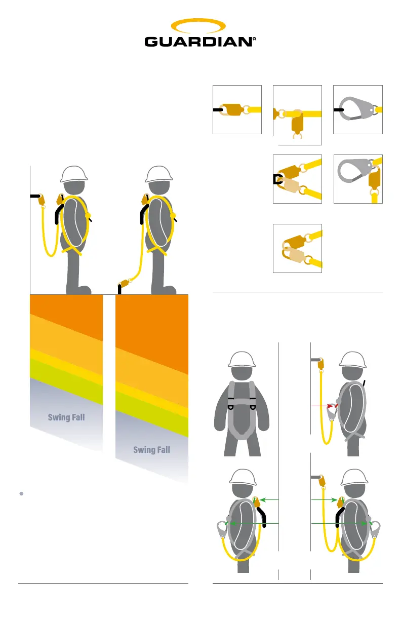
Diagram A - Fall Clearance
Fall clearance calculation shown below is
based on a standing worker falling directly
in-line with anchor point.
SAMPLE CALCULATION ONLY. ALWAYS
REFER TO CONNECTOR INSTRUCTIONS
FOR PRODUCT-SPECIFIC CLEARANCE
INFORMATION.
WARNING! Eliminate Swing Fall
whenever possible! If swing fall
exists, always account for additional
fall clearance. Example above shows
deployment distance for ANSI rated
shock absorbing lanyard.
● Free Fall
● Deceleration
● Harness Stretch
● Safety Factor
● Swing Fall
Anchor Point: Level with Dorsal D-ring
Anchor Point: At Foot-level
6’
4’
1.5’
2’
12’
5’
1.5’
2’
Anchor
Point
Lanyard
Keeper
Anchor
Point
Lanyard
Keeper
Dorsal
D-ring
Diagram C - Lanyard Keepers
Diagram B - Connections
 Loading...