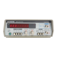
FUNCTION GENERATOR -SERIES
INSTRUCTION MANUAL
l Fig.4-2 REAR PANEL
230V
115V
INPUTS BEFORE OPENING.
TO AVOID SHOCK, REMOVE
INT EXT
TTL/CMOS
OUTPUT
DC 15V
MAX
INPUT
VCF/MOD
OUTPUT
GCV
COUNTER
MAX
CAT
INPUT
COUNTER
AC
150Vrms
250VIEC1010 CAT
AC
29W 36VA
115
18 24
T0.16A 250V
T0.315A 250V
FUSE RATING
WARNING
FUNCTION GENERATOR -SERIES
INSTRUCTION MANUAL
4. FUNCTION DESCRIPTION
1. Power Switch Connect the AC power, then press power switch.
2. Gate Time
Indicator
Press the power switch, Gate time indicator will start
to flash (the gate time of internal counter
second).
2a.
Gate Time
Selector
Press this key to change gate time when use external
counter mode. The change order is according to 0.01s,
0.1s, 1s,10s cycle by pressing these keys.
3. Over Indicator In the external counter mode, the indicator
illuminated when the output frequency is greater than
the range selected.
4. Counter Display Shows the external frequency by 6 × 0.3"
display, and shows the internal frequency by 5 × 0.3
green display.
5. Frequency
Indicator
Indicate the current frequency value.
6. Gate Time
Indicator
Indicate the current Gate time (external. counter mode
use only).
7. Frequency Range
Selector
To select the required frequency range by pressing the
relevant push button on the panel as shown in
Table 1 and Table 2.
Artisan Technology Group - Quality Instrumentation ... Guaranteed | (888) 88-SOURCE | www.artisantg.com

 Loading...
