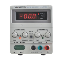
Voltage range:
19.99V of full scale (rating voltage618V).
199.9V of full scale (rating voltage>20V).
Current range:
1.999A of full scale (rating current<2A).
19.99A of full scale (rating currenta2A).
(2) Analog Type
Meter: Voltmeter and Ammeter each one.
Class: 2.5
Dimensions: 50x50
m/m.
2
-
5
Insulation
Between chassis and output terminal.
20MIR or above (DC500V).
Between chassis and AC cord.
30MR or above
(DC500V).
3.
THEORY
OF
OPERATION
The power supply consists of an AC input circuit and transformer, a bias supply consisting of a rectifier and filter and reference
voltage source, a main regulator circuit consisting of the main rectifier and filter, a series regulator, a current comparator, a voltage
comparator, a reference voltage amplifier, a remote control and a relay control circuit.
The circuit element are several of integrated circuit
(U101, U102, U103, U104, U105, U106).
The circuit arrangement is shown in block diagram from Fig. 1.
The circuit is discussed with reference to the block diagram Function Description.
Single phase input power is applied to transformer through the input circuit.
Auxiliary rectifier
D1021-Dl024 provides a bias voltage filtered by capacitor C103, C104 for the preregulator U101, Q105, Q106,
that provides a regulator voltage for element of action.
The main rectifier, a full wave bridge rectifier, provides the power which is filtered by capacitor
C101 and then regulated via
a series regulator and deliver to the output.
U105 acted as a current limiter. When current is over predominante rating, it acted and decreased the current U102 provides
a reference voltage for
U103A, U1038, U103 is
a
invertor amplifier, U105 is a current comparator. Both via
OR
gate and driver amplifier
to series control
01 01, Q102.
The relay control circuit provides limited power dissipation is series regulator.
Artisan Technology Group - Quality Instrumentation ... Guaranteed | (888) 88-SOURCE | www.artisantg.com
 Loading...