Do you have a question about the GW Instek GPS-3030D and is the answer not in the manual?
Details about the main supply, rating, dimensions, and weight of the unit.
Specifications for constant voltage mode, including regulation, recovery, and ripple.
Specifications for constant current mode, including regulation and ripple.
Description of the digital and analog indicator meters for voltage and current.
Insulation specifications for chassis to terminals and AC cord.
Overview of the power supply's internal circuitry and components through a block diagram.
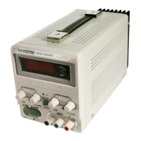
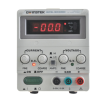
Identification and function of all controls and indicators on the front panel.
Identification and function of all connectors and switches on the rear panel.
Essential safety guidelines for installation, AC input, and output voltage handling.
Step-by-step procedure for setting the current limit protection feature.
Explanation of the automatic crossover between constant voltage and constant current modes.
Guidance on single, series, and parallel operation modes for the power supply.
Instructions for remote control of output voltage and current using external signals.
Procedure for replacing fuses and important safety warnings related to it.
Steps to convert the unit for operation with different input AC line voltages.
Detailed procedures for adjusting rating voltage and rating current calibration.
Guidelines on how to clean the power supply unit safely and effectively.
| Output Voltage | 0-30V |
|---|---|
| Output Current | 0-3A |
| Power Rating | 90 W |
| Line Regulation | ≤0.01% + 3mV |
| Ripple & Noise | ≤1mVrms |
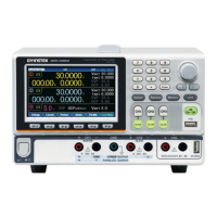
| Output Channels | 3 |
| Ripple & Noise (CC, CH1/CH2) | ≤3mArms |
| Load Regulation | 0.01% + 5 mV |
| Voltage Regulation (CH1/CH2) | ≤0.01% + 3mV |
| Protections | Overvoltage |
| Cooling | Fan |
| Operating Temperature | 0 to 40 °C |
| Storage Temperature | -20°C to 70°C |
| Input Voltage | 100 to 240 V AC |