EasyManua.ls Logo

GW Instek GPS-3303 User Manual

GW Instek GPS-3303
18 pages
To Next Page IconTo Next Page
Page #1 background imageLoading...
Page #1 background image
PS-2303GD1BH
Specifications subject to change without notice.
OUTPUT MODE
CONSTANT VOLTAGE
OPERATION
(CH1, CH2)
CONSTANT CURRENT
OPERATION
(CH1, CH2)
TRACKING OPERATION
(CH1, CH2)
GPS-4303
2.2V ~ 5.2V OUTPUT (CH3)
GPS-3303
5V FIX OUTPUT (CH3)
GPS-4251
3V~6V OUTPUT(CH3)
GPS-4303
8V ~ 15V OUTPUT (CH4)
GPS-4251
8V~15V OUTPUT (CH4)
METER
INSULATION
POWER SOURCE
ACCESSORIES
DIMENSIONS & WEIGHT
Voltage
Current
Tracking Series Voltage
Tracking Parallel Current
Line Regulation
Load Regulation
Ripple & Noise
Recovery Time
Line Regulation
Load Regulation
Ripple & Noise
Tracking Error
Series Regulation
Load Regulation
Ripple & Noise
Line Regulation
Load Regulation
Ripple & Noise
Current Output
Line Regulation
Load Regulation
Ripple & Noise
Current Output
Digital
Chassis and Terminal
Chassis and AC Cord
AC 100V/120V/220V(+10%)/230V(+10%~-6%), 50/60Hz
255(W) x 145(H) x 265(D) mm, Approx. 7 kg (GPS-4303/3303/2303) ; Approx. 6.3kg (GPS-4251)
Instruction manual x 1 Power cord x 1,
GPS-4303 : Test lead GTL-104 x 2, GTL-105 x 2 or GTL-203 x 2, GTL-204 x 2
GPS-4251 : Test lead GTL-105 x 4 or GTL-203 x 4
GPS-3303 : Test lead GTL-104 x 2, GTL-105 x 1 or GTL-203 x 1, GTL-204 x 2
GPS-2303 : Test lead GTL-104 x 2 or GTL-204 x 2
CH1
CH1
CH1 CH1
CH3
CH3
GPS-4303 GPS-4251 GPS-3303
GPS-2303
CH4
CH4
CH2
CH2
CH2 CH2CH3
0 ~ 30V
0 ~ 25V
0 ~ 30V 0 ~ 30V
2.2 ~ 5.2V
3 ~ 6V8 ~ 15V 8 ~ 15V
0 ~ 3A
0 ~ 0.5A
0 ~ 3A 0 ~ 3A
1A Max.
2.5A Max.
1A Max.
1A Max.
3A Max.
5V Fixed
0 ~ 60V
0 ~ 50V
0 ~ 60V 0 ~ 60V
- - - -
- - - - - - - -
0 ~ 6A
0 ~ 1A
0 ~ 6A 0 ~ 6A
< 0.01% + 3mV
< 0.01% + 3mV (rating current < 3A)
< 0.02% + 5mV (rating current > 3A)
< 1mVrms , 5Hz ~ 1MHz
< 100 S (50% Load change, Minimum load 0.5A)
< 0.2% + 3mA
< 0.2% + 3mA
< 3mArms
< 0.5% + 10mV of the CH1
< 300mV
< 0.01% + 3mV
< 2mVrms , 5Hz ~ 1MHz
< 5mV
< 15mV
< 2mVrms, 5Hz ~ 1MHz
GPS-4303: 1A, GPS-3303: 3A, GPS-4251: 2.5A
< 5mV
< 10mV
< 2mVrms, 5Hz ~ 1MHz
1A
3 digits 0.5" LED display
GPS-4303/4251/3303 Out ON Accuracy + (0.5% rdg + 2 digits)
GPS-4303/3303 Out OFF Accuracy + (0.5% rdg + 8 digits)
GPS-2303 Accuracy + (0.5% rdg + 2 digits)
> DC 500V / 20M
> DC 500V / 30M
SPECIFICATIONS
GOOD WILL INSTRUMENT CO., LTD.
No. 95-11, Pao-Chung Road, Hsin-Tien City,
Taipei Hsien, Taiwan, R.O.C.
Tel:+886-2-29179188 Fax:+886-2-29179189
http://www.goodwill.com.tw
INSTEK CORP.
U.S.A.
GOOD WILL Southeast Asia Sdn. Bhd.
MALAYSIA
GOOD WILL Instrument(Suzhou)Co.,Ltd.
CHINA
1205 John Reed Court No. 5-3-11, Hunza Complex, NO.69, Lushan Road, Suzhou New District,
Jiangsu, ChinaCity of Industry, CA 91745, U.S.A. Jalan Gangsa, Greenlane Heights,
11600 Penang, MalaysiaTel : +1-626-3366537
Fax : +1-626-3691748
Tel : +60-4-6591988
Fax : +60-4-6591989
Tel : +86-512-66617177
Fax : +86-512-66617277
http://www.instek.com
E-mail: marketing@goodwill.com.tw
Type of Test Lead Set
Test Lead GTL-104 : Current 4A~10A
Test Lead GTL-105 : Current 3A
Test Lead GTL-203 : Current 3A
Test Lead GTL-204 : Current 4A~10A
Standard Accessories
GPS-4303 4-channels, 0~30V x 2 , 0~3A x 2 , Power Supply
GPS-4251 4-channels, 0~25V x 2 , 0~0.5A x 2 , Power Supply
GPS-3303 3-channels, 0~30V x 2 , 0~3A x 2 , Power Supply
GPS-2303 2-channels, 0~30V x 2 , 0~3A x 2 , Power Supply
Order Information
GPS-4303-01 Including GTL-104 x 2 & GTL-105 x 2
GPS-4303-02 Including GTL-203 x 2 & GTL-204 x 2
GPS-4251-03 Including GTL-105 x 4
GPS-4251-04 Including GTL-203 x 4
GPS-3303-05 Including GTL-104 x 2 & GTL-105 x 2
GPS-3303-06 Including GTL-203 x 2 & GTL-204 x 2
GPS-2303-07 Including GTL-104 x 2
GPS-2303-08 Including GTL-203 x 2
Instruction manual x 1
Power cord x 1
Question and Answer IconNeed help?

Do you have a question about the GW Instek GPS-3303 and is the answer not in the manual?

GW Instek GPS-3303 Specifications

General IconGeneral
ModelGPS-3303
TypeLinear DC Power Supply
Output Channels3
Output Voltage (Channel 3)5 V
Output Current (Channel 3)3 A
Ripple & Noise (CV)≤ 1mVrms
Ripple & Noise (CC)≤ 3mArms
Load Regulation (CV)≤ 0.01% + 3mV
Display TypeLED
Output Voltage (Channel 1 & 2)0 to 30 V
Output Current (Channel 1 & 2)0 to 3 A
ProtectionsOverload
Operating Temperature0°C to 40°C
Input Voltage50/60Hz

Summary

Safety Terms and Symbols

Introduction

Specifications

General

Details general operating conditions, environmental parameters, and installation category.

Operation Mode

Covers independent, series, and parallel operation modes for the power supplies.

Constant Voltage Operation

Specifies output voltage range, line regulation, load regulation, and ripple for CV mode.

Constant Current Operation

Details output current range, regulation, and ripple for CC mode.

Tracing Operation

Describes tracking error and regulation for series and parallel tracking modes.

Meter

Information on meter types, accuracy, and display specifications for voltage and current.

CH3 Output Specifications

Specific voltage range, regulation, ripple, and current capacity for the CH3 output.

CH4 Output Specifications

Specific voltage range, ripple, and current capacity for the CH4 output.

Insulation

Electrical insulation resistance values between chassis and terminals.

Theory of Operation

Panel Controls and Indicators

Front Panel

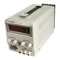
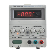
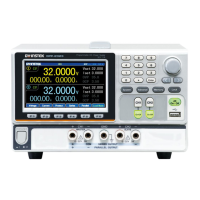
Identifies and describes the controls and indicators on the front panel of the unit.

Real Panel

Identifies and describes the connections, switches, and connectors on the rear panel.

Operation Instruction

Precaution

Important safety and operational warnings before using the power supply.

Setting Current Limit

Step-by-step guide for safely setting the output current limit.

Constant Voltage/Constant Current Characteristics

Explains the automatic crossover between CV and CC modes with load changes.

Operation Mode

Instructions for using the power supply in independent, series, and parallel modes.

CH3 Power Supply Operation

Detailed setup and operational procedures for the CH3 output channel.

CH4 Power Supply Operation

Detailed setup and operational procedures for the CH4 output channel.

Dynamic Load Operation & Application

Guidelines and applications for using the power supply with dynamic loads.

Output ON/OFF Action

Explains how to control the output state using the main power switch.

Fan Control

Information regarding the cooling fan's operation and temperature management.

Maintenance

Fuse Replacement

Procedure for safely replacing blown fuses in the unit.

Line Voltage Conversion

Instructions on how to change the unit's input AC voltage setting.

Adjustments

Calibration and adjustment procedures to ensure output accuracy.

Cleaning

Recommended methods for cleaning the instrument safely and effectively.

Related product manuals