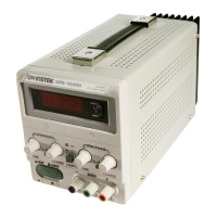
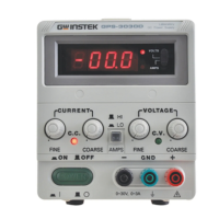
The Instek GPS-S Series (Analog/Digital Type) is a regulated DC power supply designed for laboratory, school, and production line applications. It offers a full-service, independent repair center with experienced engineers and technicians on staff, and Artisan Technology Group also purchases excess, underutilized, and idle equipment, offering credit for buybacks and trade-ins. Custom engineering services are available to ensure equipment works exactly as specified. Artisan Technology Group provides critical and expedited services, in-stock and ready-to-ship items, leasing/rentals/demos, and ITAR-certified secure asset solutions, backed by an expert team, trust guarantee, and 100% satisfaction.
Function Description
The power supply provides a continuously adjustable output voltage from 0 to its rated voltage, and the load current can be adjusted from 0 to its rated current using coarse and fine potentiometers. Both output voltage and current can be accurately read on the built-in voltmeter and ammeter. The unit operates as either a constant voltage or constant current source, with automatic crossover between these modes depending on the load. This automatic crossover characteristic allows for continuous transition between constant current and constant voltage modes in response to load changes. The intersection of these modes is called the crossover point, indicated by the front panel LED indicators (CV indicator off, CC indicator on). For applications requiring higher voltage or current, multiple units can be connected in series or parallel. The device also supports remote control of output voltage and current using an external voltage source.
Important Technical Specifications
General:
- Main Supply: 100V/120V/220V/240V ±10% 50/60 Hz (Switch selectable)
- Operation Environment: Indoor use, Altitude up to 2000 m, Installation Category II, Pollution degree 2
- Operation Temperature & Humidity: 0°C to 40°C, <80%
- Storage Temperature & Humidity: -10°C to 70°C, <70%
- Dimensions: 128 (W) X 145 (H) X 285 (D) mm
- Operation Mode: Single or Tracking (Series or Parallel) operation (two units).
Model-Specific Ratings (Max. Rating, Input Rating, FUSE Type and Rating, Weight):
- GPS-1830/GPS-1830D: 18V, 3A; 120 Watts, 150 VA; 100V/120V: T 2A 250V, 220V/240V: T 1A 250V; 4.0 Kg
- GPS-1850/GPS-1850D: 18V, 5A; 190 Watts, 230 VA; 100V/120V: T 2.5A 250V, 220V/240V: T 1.25A 250V; 5.5 Kg
- GPS-3030/GPS-3030D: 30V, 3A; 160 Watts, 200 VA; 100V/120V: T 2.5A 250V, 220V/240V: T 1.25A 250V; 5.0 Kg
- GPS-6010: 60V, 1A; 120 Watts, 150 VA; 100V/120V: T 2A 250V, 220V/240V: T 1A 250V; 4.0 Kg
Constant Voltage Operation:
- Output Voltage Range: 0 to rating voltage continuously adjustable.
- Voltage Regulation:
- Line regulation: ≤0.01%+3mV.
- Load regulation: ≤0.01%+3mV (rating current≤3A), ≤0.01%+5mV (rating current>3A).
- Recovery Time: ≤100µs (50% Load change, minimum load 0.5A).
- Ripple & Noise: ≤0.5mVrms (5Hz~1MHz) (rating current≤3A), ≤1.0mVrms (5Hz~1MHz) (rating current>3A).
- Temperature Coefficient: ≤300PPM/°C.
Constant Current Operation:
- Output Current Range: 0 to rating current continuously adjustable.
- Current Regulation:
- Line regulation: ≤0.2%+3mA.
- Load regulation: ≤0.2%+3mA.
- Ripple & Noise: ≤3mArms.
Indicator Meter:
- Digital Type:
- Display: 3 1/2 Digits 0.5" Red LED DISPLAY (Voltage and current switchable).
- Accuracy: ±(0.5% of rdg + 2 digits).
- Voltage range: 19.99V (rating voltage≤18V), 199.9V (rating voltage>20V).
- Current range: 1.999A (rating current<2A), 19.99A (rating current≥2A).
- Analog Type:
- Meter: Voltmeter and Ammeter each one.
- Class: 2.5.
- Dimensions: 50x50 m/m.
Insulation:
- Between chassis and output terminal: 20MΩ or above (DC500V).
- Between chassis and AC cord: 30MΩ or above (DC500V).
Usage Features
Front Panel Controls:
- CV/CC indicators: Lights when operating in constant voltage or constant current mode.
- Voltage coarse/fine: Adjusts output voltage.
- Current coarse/fine: Adjusts output current.
- Output terminals (+, -, GND): Positive, negative, and earth/chassis ground connections.
- Meter: Displays output voltage or current (Analog or Digital type, switchable).
- Power control: On/off switch.
- Current HI/LO control: Selects current range.
Rear Panel Controls:
- Fuse holder: Contains the protective fuse.
- Power cord: Connects to AC supply.
- AC selects switch: Selects input line voltage (100V/120V/220V/240V).
- Master-Slave Switch: Selects for Master (internal control) or Slave (external remote control) tracking operation.
- Input-Output connector: Used for connecting Master and Slave units in series or parallel.
Operation Modes:
- Single Operation: Standard use of the power supply.
- Series Operation (for higher voltage): Two units can be connected in series. The Master unit's "SER" output connects to the Slave unit's "SER" input. The Master-Slave switch on the Master unit is set to "INT" and on the Slave unit to "SER-SLAVE". WARNING: Voltages over 60V DC are a lethal shock hazard.
- Parallel Operation (for higher current): Two units can be connected in parallel. The Master unit's "PAR" output connects to the Slave unit's "PAR" input. The Master-Slave switch on the Master unit is set to "INT" and on the Slave unit to "PAR-SLAVE". The Master output voltage should be set 0.2-0.5V lower than the Slave output voltage.
- Remote Control of Output Voltage: An external voltage source (0-10V) can control the output voltage. The control voltage source's "+" line connects to the "SER" input terminal, and its "-" line connects to the power supply output "+" terminal.
- Remote Control of Output Current: An external voltage source (0-10V) can control the output current. The control voltage source's "-" line connects to the "PAR" input terminal, and its "+" line connects to the power supply output "+" terminal.
Maintenance Features
Fuse Replacement:
- If the fuse blows, the CV or CC indicators will not light, and the power supply will not operate.
- The fuse is located on the rear panel.
- Always determine and correct the cause of the blown fuse before replacing it.
- WARNING: Replace fuse only with a 250V fuse of the specified type and rating, and disconnect the power cord before replacement.
Line Voltage Conversion:
- The power transformer's primary winding is tapped for operation at 100V, 120V, 220V, or 240V AC (50/60 Hz).
- To convert to a different line voltage:
- Ensure the power cord is unplugged.
- Change the AC selects switch on the rear panel to the desired line voltage position.
- A change in line voltage may require a corresponding change of fuse value; install the correct fuse as listed on the rear panel.
Adjustments:
- The unit is factory-adjusted. Readjustment is only recommended if repairs affecting accuracy have been made or if the unit is believed to be out of adjustment.
- A multimeter with an accuracy of ±0.1% DCV or better (e.g., GOODWILL Model GDM-8035G) is required for adjustments.
- Procedures are provided for adjusting rating voltage and rating current, including specific trimmer potentiometers (VR105, VR301/VR201, VR107, VR108, VR109, VR110/VR111).
Cleaning:
- Use a soft cloth dampened with a mild detergent and water.
- Do not spray cleaner directly onto the instrument.
- Avoid chemicals like benzine, benzene, toluene, xylene, acetone, or similar solvents.
- Do not use abrasive cleaners.