5
-
4
Operation
Mode
$
(1)
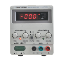
Single Operation
Use the supply as it is for single operation.
A.
Set Power switch to
"
OFF
"
position.
B. Make sure that line voltage is correct for the input power voltage.
C. Plug power cord into the power outlet.
D.
Set Power switch to
"
ON
"
position.
E. Adjust
"
Voltage
"
and
"
Current
"
control to the desired output voltage and current.
F. Connect the external load to the output binding posts. Make sure both
"+"
and
"-"
terminals are connect correctly.
(2)
Series Operation
(
or~ly applied
to
the same models
)
Two power supplies can be connected in series to provide higher voltage and rating current output. See Fig.
5
-
2
for the
connection scheme.
A. Set power switch to
"
OFF
"
position.
B.
Set the
"
MASTER
"
power supply INT
-
SLAVE switch to
"
INT
"
position and set the
"
SLAVE
"
power supply INT
-
SLAVE
switch to
"
SER
-
SLAVE
"
position.
C.
From the
"
MASTER
"
power supply
"
SER
"
output terminal to
"
SLAVE
"
power supply
"
SER
"
input.
D.
Set power switch to
"
ON
"
position.
A
WARNING. Voltage more than
60V
DC
are a lethal shock hazard to the user. Be careful when connecting
power supplies in series to achieve voltage higher than
60V
DC
total or
60V DC
between any connection and
earth ground.
Artisan Technology Group - Quality Instrumentation ... Guaranteed | (888) 88-SOURCE | www.artisantg.com
 Loading...