LCR-800 Series User Manual
12
SPEED
SLOW
DISPLAY
VALUE
MODE
L/Q
CIRCUIT
SERIES
MENU
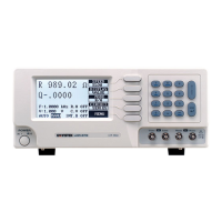
L 1.2345H
Q 0.6789
TESTING
F : 1.000 kHz
V : 1.000 V
AUTO MANU INT.B OFF
R.H OFF
C.V OFF
Press
F3
key
successively in order
to select the different
measurement mode
(L/Q, C/D, C/Q, R/Q)
Primary
Display
Secondary
Display
Figure 4-3. Primary & Secondary display
User can select R/Q for resistor measurement; select L/Q for inductor
measurement; select either C/D or C/R for capacitor measurement.
4-4-2. Series & Parallel Equivalent Circuit
Impedance that is neither a pure resistance nor a pure reactance can be
represented at any specific frequency by either a series or a parallel combination
of resistance and reactance. Such representation is called “equivalent circuit”.
The component value of the “Primary Display” depends on which equivalent
circuit (series or parallel) is chosen. In normal, the component manufacturer
shall specify how a component is to be measured (usually series) and at what
frequency.
Suggested Test Conditions:
Inductors less than 10µH: Series, 100kHz.
Inductors from 10 µH to 1mH: Series, 10kHz.
Inductors from 1mH to 1H: Series, 1kHz.
Inductors greater than 1H: Series, 0.1kHz.
Capacitors less than 10pF: Parallel, 100kHz.
Capacitors from 10 to 400pF: Series or Parallel, 10kHz.
Capacitors from 400 to 1µF: Series, 1kHz.
Capacitors greater than 1µF: Series, 0.1 or 0.12kHz.
Resistor less than 1kΩ: Series, 1kHz.
Resistor from 1kΩ to 10MΩ: Parallel, 0.25kHz.
Resistor greater than 10 MΩ: Parallel, 0.03kHz
 Loading...