Do you have a question about the GW Instek LCR-1100 and is the answer not in the manual?
Explains safety symbols used in the manual and on the instrument.
Provides essential safety precautions for operating the LCR meter.
Covers safety for power supply, battery, and cleaning procedures.
Specifies operation/storage environments and product disposal guidelines.
Introduces the LCR-1000 series, its models, features, and specifications.
Describes the key features and capabilities of the LCR-1000 series instrument.
Lists the standard and optional accessories included with the instrument.
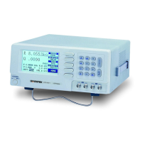
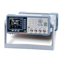
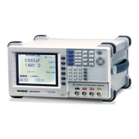
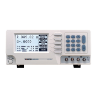
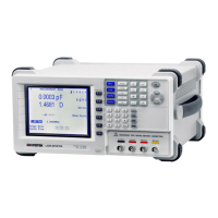
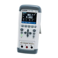
Details the components and controls located on the front panel of the instrument.
Explains the function of each button and connector on the front panel.
Identifies and describes the ports and controls on the top panel of the instrument.
Lists test functions and explains equivalent circuit concepts.
Covers test frequency, level, output impedance, and range specifications.
Details measurement speeds, basic accuracy, and display ranges for measurements.
Covers system configuration, communication interfaces, and comparator functionality.
Describes how the LCD displays battery level and charging status.
Guides on using the keypad for entering nominal values via the touch screen.
Explains how to input the nominal value by measuring a standard component.
Details the steps for performing open circuit correction and its purpose.
Details the steps for performing short circuit correction and its purpose.
Describes the process and expected results of the open circuit correction.
Describes the process and expected results of the short circuit correction.
Explains how to view instrument model, serial number, and firmware versions.
Mentions the engineering mode which is not for user operation.
Provides a detailed guide on calibrating the touch screen using a touch pen.
Describes the final steps and confirmation of touch screen calibration.
Offers important notes and precautions for measuring capacitors accurately.
Explains how connecting to a PC ensures measurement accuracy by using battery power.
Details the setup and communication parameters for the USB-VCOM virtual serial port.
Describes the USB-HID class for automatic identification and control via PC.
Explains key API functions for HID communication and provides system compatibility notes.
Illustrates the flowchart for establishing a remote control connection with the instrument.
Details the structure and format of command packets sent via USB-HID.
Explains the special characters used as specifiers in command descriptions.
Lists and describes the data formats and magnifications used in commands.
Provides a comprehensive list of all available USB commands and their parameters.
Lists further commands for control switches, version query, and error handling.
Explains commands for setting display page and outputting strings.
Details commands for setting measurement parameters and equivalent modes.
Covers commands for setting and querying LCR, DCR, and auto-range modes.
Details commands for setting frequency, speed, and querying test results.
Describes commands for comparator, beep settings, and nominal value input.
Details commands for setting tolerance and querying correction switch status.
Explains commands to execute LCR and DCR open/short circuit corrections.
Describes commands to lock/unlock the keypad and hold/release screen data.
Explains commands for querying instrument identification and error messages.
Lists conditions required to achieve basic measurement accuracy.
Outlines general characteristics including operating environment, storage, and power.
Details operating power, battery life, charging, dimensions, and weight.
Covers display type, backlight, auto power off, functions, and counts.
Lists basic accuracy, range, speed, level, frequency, output impedance, and interface types.
Explains accuracy guarantees based on terminal socket type and test fixture connection.
Details how test cable length and frequency affect measurement accuracy.
Provides detailed accuracy tables for Capacitance (C) and Dissipation Factor (D) at various frequencies.
Provides detailed accuracy tables for Inductance (L) and Quality Factor (Q) at various frequencies.
Provides detailed accuracy tables for Impedance (Z) and Phase Angle (Theta) at various frequencies.
Explains the formulas for calculating ESR and Phase Angle accuracy.
Provides detailed accuracy tables for DC Resistance (DCR) measurements.
Displays the physical dimensions of the LCR-1000 series instrument.
| Type | LCR Meter |
|---|---|
| Test Frequency | 100 Hz, 120 Hz, 1 kHz, 10 kHz, 100 kHz |
| Weight | 2.5 kg |
| Equivalent Circuit | Series, Parallel |
| Measurement Parameters | L, C, R, D, Q, Z |
| Test Signal Level | 0.3Vrms, 1.0Vrms |
| Display Range (R) | 0.0001Ω to 99.99MΩ |
| Display | LCD |
| Interfaces | RS-232 |
| Power Supply | 100V ~ 240V AC, 50/60Hz |
| Measurement Speed | Fast, Medium, Slow |