
R
rgonzalezAug 3, 2025
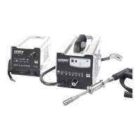
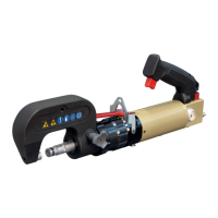
What to do if the rivet is not in place in my GYS Tools riveting machine?
- Llisa20Aug 4, 2025
If the rivet is not in place when using your GYS Tools riveting machine, it could be due to several reasons. The mandrel or matrix might be faulty, requiring replacement. Glue on the mandrel or inside the matrix can also cause this issue, so cleaning it off is recommended. Insufficient pressure, possibly from low or poorly adjusted air pressure, could be another cause. Finally, ensure that you are using the correct rivet length as per the manufacturer's instructions.