7-1
7 Priority Mapping Configuration
This chapter includes these sections:
z Introduction to Packet Precedences
z Priority Mapping Overview
z Priority Mapping Configuration Task List
z Configuring Priority Mapping
z Displaying and Maintaining Priority Mapping
z Priority Mapping Configuration Example
Introduction to Packet Precedences
IP Precedence and DSCP Values
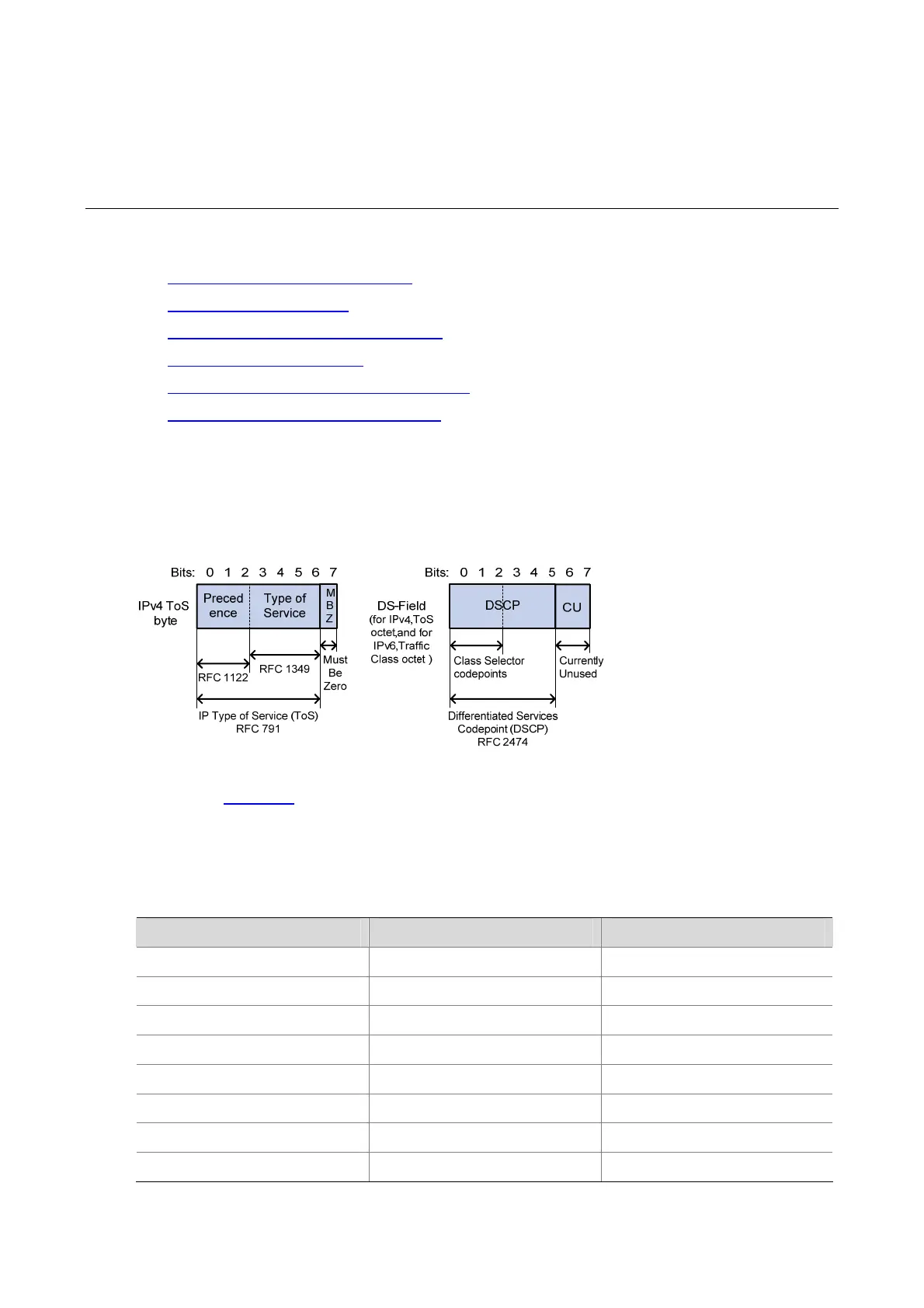
Figure 7-1 ToS and DS fields
As shown in
Figure 7-1, the ToS field of the IP header contains eight bits, and the first three bits (0 to 2)
represent IP precedence from 0 to 7. According to RFC 2474, the ToS field of the IP header is redefined
as the differentiated services (DS) field, where a DSCP value is represented by the first six bits (0 to 5)
and is in the range 0 to 63. The remaining two bits (6 and 7) are reserved.
Table 7-1 Description on IP precedence
IP precedence (decimal) IP precedence (binary) Description
0 000 Routine
1 001 priority
2 010 immediate
3 011 flash
4 100 flash-override
5 101 critical
6 110 internet
7 111 network
 Loading...