Eclipse Installation, Commissioning & Operating Manual Approved Document Ref: UI-ECL-01 Issue 8.0
25
SETUP & PROGRAMMING
Use button 2 to change the response
to ON or OFF, indicated by the amber
fault LEDs.
Then use button 1 again to scroll to
the next function if required.
Press the ENTER button to return
back to sounder circuit selection,
indicated by a steady re LED.
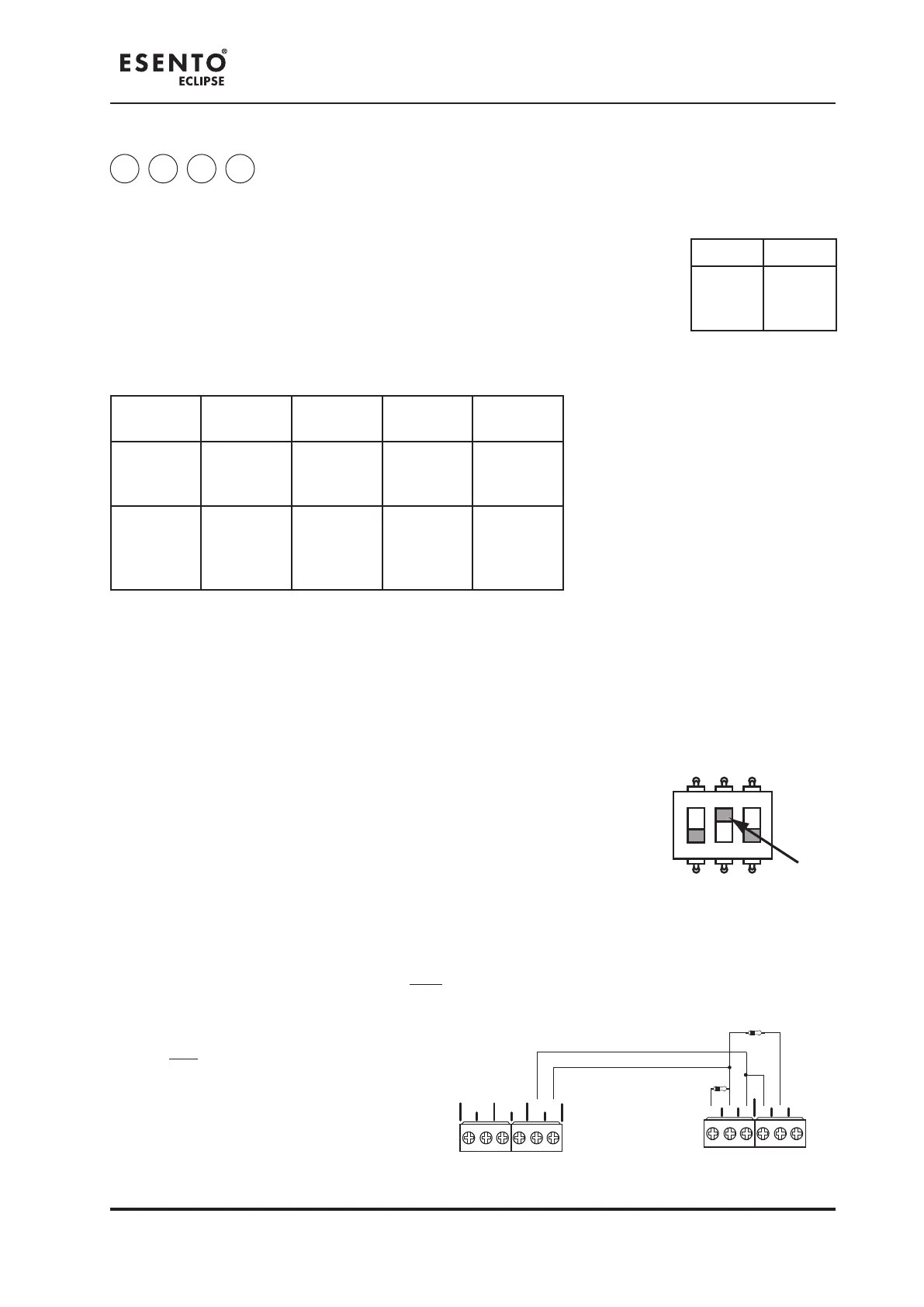
This is a special setting to congure the last zone on the panel, (i.e. zone 2 on the ECL-2 or zone 4 on the
ECL-4), to be used for interconnection from other control panels.
The function is enabled by setting switch 2 on the 3 way DIL switch located on the main PCB to the ‘ON’
position.
With switch 2 in the ‘ON’ position, the last zone becomes;
1. 1. Non latching &Non latching &
2. 2. Non aux operating.Non aux operating.
Note:
If the control panel is also set to Twin Wire mode (Switch 1 ‘ON’) and sounders are connected to the
interface zone circuit, the following sounder operation will apply:
A re (470Ω) signal to the interface zone will NOT operate the sounders connected to that Twin Wire circuit.
All other conventional (SNDR1 & SNDR2) and Twin Wire zone sounders will operate as normal.
A re (470Ω) signal to any other zone will
operate ALL conventional (SNDR1 & SNDR2)
and Twin Wire sounder circuits, including the
sounders connected to the interface zone, as
normal.
ZONE INTERFACE FUNCTION
1 2 3
ON
+ - + - + -
ZONE2 ZONE3 ZONE4
C NC NO
NO
C NC
FIRE
FAULT
(optional)
PANEL 1 PANEL 2
470Ω
3K3Ω
Example connection
4 3 4 4
Conventional sounder circuit functional options
This option is used to programme each of the conventional sounder circuits on the main circuit board with
custom reponses as below.
Enter the above code and press ENTER. Then use button 1 to select the sounder
circuit to be programmed (indicated by a steady re zone LED) as per table.
With the required sounder LED lit, press the ENTER button. Fire zone LED 1 will now
pulse. This indicates setting up function 1 (resets on silence alarms) for the selected
circuit. Use button 1 to scroll to the required function, indicated buy pulsing re LEDs 1- 4 as per table
below.
LED 1 LED 2
SNDR1
(Main
PCB)
SNDR2
(Main
PCB)
Fire LED
(pulsing)
LED 1 LED 2 LED 3 LED 4
Function
Resets on
Silence
Alarms
Activates
on
Evacuate
Activates
on Class
Change
Activates
on Alert
Amber
fault LED
(default
setting)
OFF ON OFF OFF