Excel-EN Installation, Commissioning & Operating Manual Approved Document Ref: UI-XLEN-01 Issue 7.0
13
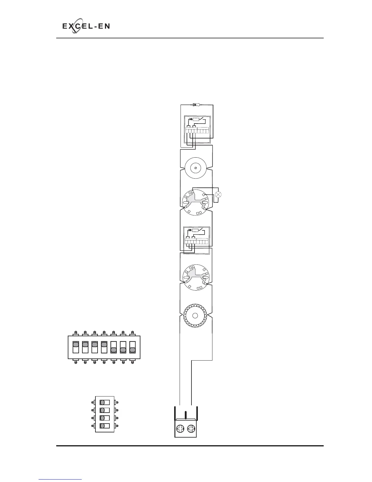
DESIGN CONSIDERATIONS
GENERAL TWIN WIRE SYSTEM SCHEMATIC
-VE
E
R+
R
+
R
-
R
-
R
E
M
O
T
E
IN
D
IC
A
TO
R
R
IL
58
+
_
Typical Twin Wire
Circuit Wiring
4K7 OHM
END OF LINE
RESISTOR
Note:
On a Twin Wire circuit
the sounders are connected in reverse polarity
to the detectors and call points
Note:
Each zone circuit configuration
is set to ‘Conventional’ by default.
‘Twin Wire’ mode must be set zonally
using DIL switches 1-4 on the Main PCB.
Or switches A, B, C & D on the zone
extension PCBs.
-
+
ZONE 1
APOLLO TWIN WIRE BASE
45681-206
APOLLO TWIN WIRE BASE
45681-206
TWIN WIRE CALL POINT
MCP1B-R-TW
TWIN WIRE CALL POINT
MCP1B-R-TW
1
2
3
4
_
_
++
470
1
2
3
4
_
_
++
470
-VE
+VE
MOTORISED BELL
POLARISED
ELECTRONIC SOUNDER
POLARISED
+VE
+VE
-VE
-VE
+VE
1 2 345
67
ON
1 2 34
ON
D
C
B
A
TWIN