Excel-EN Installation, Commissioning & Operating Manual Approved Document Ref: UI-XLEN-01 Issue 7.0
18
SETUP & PROGRAMMING
NETWORK PANELS SETUP
The system can support up to 8 networked control panels, 1 x Master and up to 7 x Slaves.
Comms PCB
To run a network, a Comms PCB (TPCA05) must be fi tted to each control panel. Any Excel-EN or Excel-32
panel from 2 to 32 zones with software version 4.0 and above may be used.
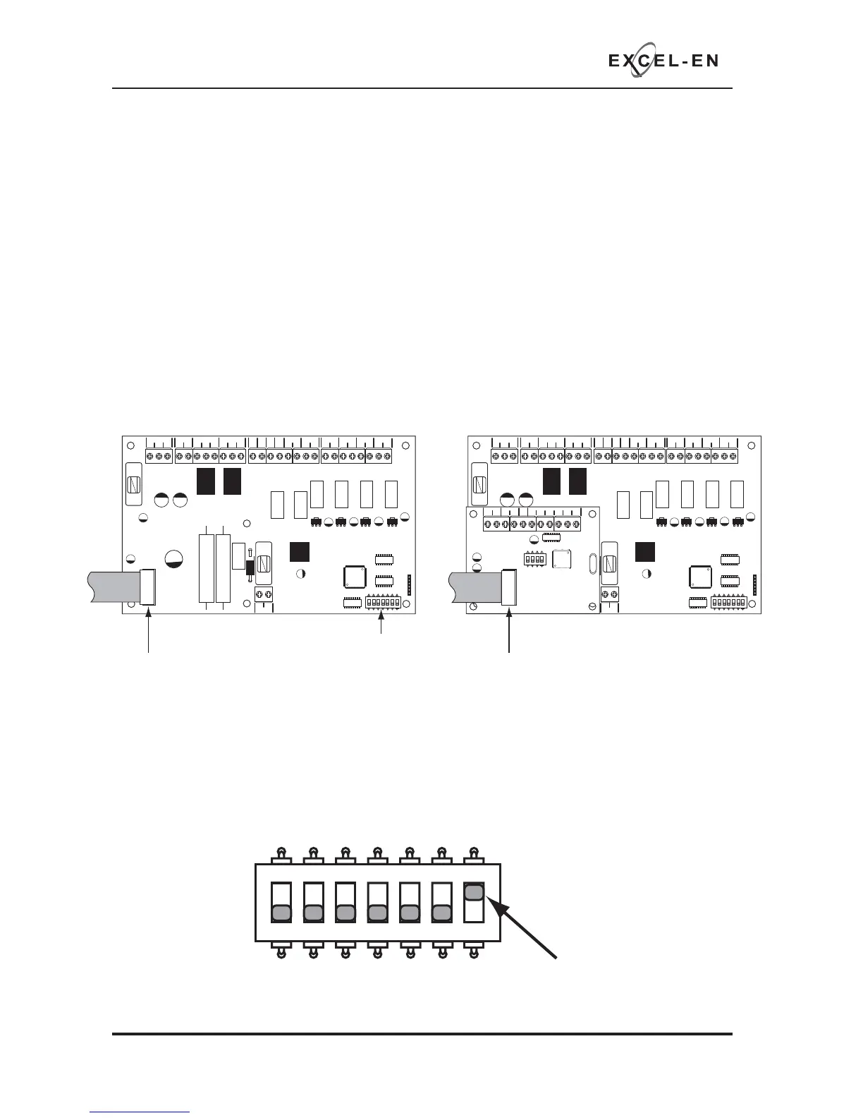
The Comms PCB fi ts into the control panel on top of the main circuit board where the ribbon cable from
the display board comms is normally plugged.
To fi t the Comms PCB, power down the panel, un-plug the display board ribbon cable from the main circuit
board and plug the Comms PCB into the socket instead.
A socket is provided on the top of the Comms PCB to re-connect the display board ribbon cable.
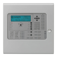
Each panel to be included in the network is defi ned by setting a switch on the main PCB. In the case of
the Excel-EN this is switch 7 on the 7 way DIL switch. OFF = Stand Alone mode, ON = Network/Repeater
mode.
With this switch in the ON position the panel will automatically recognise & operate the Comms PCB
(TPCA05).
PSU
@+
+
-- +-
+-
+- +- +-+- +-
28V 0V
C NC NO C NC NO
FIRE FAULT
FR
FLT
CC
PUL
-OP -OP -IP -IP
SNDR1 SNDR2 ZONE1 ZONE2 ZONE3 ZONE4
BATTERY
PSU
@+
+
-- +-
+-
+- +- +-+- +-
28V 0V
C NC NO C NC NO
FIRE FAULT
FR
FLT
CC
PUL
-OP -OP -IP -IP
SNDR1 SNDR2 ZONE1 ZONE2 ZONE3 ZONE4
BATTERY
COMS A COMS B 28
V+
SW -ve OUTPUTS
+-
+-
12345 6
1 2 34
ON
ADDRESS
Disconnect display board ribbon cable
7 way DIL switch
Plug Comms PCB into the socket and
re-connect dispay board ribbon cable to
socket on top of Comms PCB
1 2 345
67
ON
1 2 345
67
ON
ON = Network/
Repeater mode
1 2 345
67
ON