Excel-EN Installation, Commissioning & Operating Manual Approved Document Ref: UI-XLEN-01 Issue 7.0
19
SETUP & PROGRAMMING
Programming
The Master panel will need to be programmed for the number of network panels on the system. See panel
wide programming settings, code 2-1-2-3, option 10, (Set Number of Network Slave Panels on System).
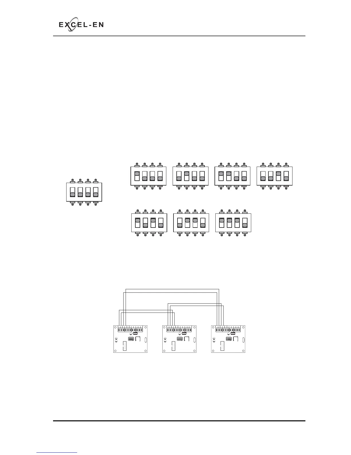
Addressing
Each panel needs to have a unique address. The addressing is done using the 4 DIL switches on each of
the Comms PCBs using binary code values, see diagram below.
The addresses should be set in sequence from 1 - 8, fi rst slave panel = address 01, second slave panel =
address 02 etc.
The Master panel is defi ned by being address 00 (all switches off).
Network slave panels and/or repeater panels are designed to be wired in a fault tolerant (fail safe) loop
confi guration, from comms A to B and back to the Master panel again (see drawing below). This enables
the network to still function if there is a break in the cables.
If replacing an older system where the existing cabling cannot be confi gured in a loop as above, it is
possible to change the panel settings to legacy, radial circuit comms monitoring.
See panel wide programming settings, code 2-1-2-3, option 6, (Change Network/Repeater Comms
Monitoring Type).
1 2 34
ON
ADD 01
1 2 34
ON
ADD 02
1 2 34
ON
ADD 03
1 2 34
ON
ADD 04
1 2 34
ON
ADD 05
1 2 34
ON
ADD 06
1 2 34
ON
ADD 07
SLAVE PANEL 1
SLAVE PANEL 5 SLAVE PANEL 6 SLAVE PANEL 7
1 2 34
ON
ADD 00
MASTER PANEL
SLAVE PANEL 2 SLAVE PANEL 3 SLAVE PANEL 4
COMS A COMS B 28
V+
SW -ve OUTPUTS
+-
+-
12345 6
1 2 34
ON
ADDRESS
COMS A COMS B 28
V+
SW -ve OUTPUTS
+-
+-
12345 6
1 2 34
ON
ADDRESS
COMS A COMS B 28
V+
SW -ve OUTPUTS
+-
+-
12345 6
1 2 34
ON
ADDRESS
Fault Tolerant Loop Wiring
Master Panel Slave/Repeater Panel 1 Slave/Repeater Panel 2
 Loading...