Excel-EN Installation, Commissioning & Operating Manual Approved Document Ref: UI-XLEN-01 Issue 7.0
20
SETUP & PROGRAMMING
TWIN WIRE MODE
What is Twin Wire?
Twin Wire is what is often referred to as sav wire. The technology enables sounders and beacons to
be connected to the same circuit as the detectors and call points. This can result in greatly reduced
installation time and cost.
How does it work?
In Twin Wire confi guration the fi re zone circuits reverse polarity in alarm condition to power the sounders
and beacons. For this reason the sounders and beacons need to be wired in opposite polarity to the
detectors and call points, i.e. zone positive wire connects to detector base and call point positive terminals
but sounder and beacon negative terminals.
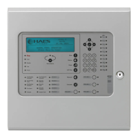
1 2 345
67
ON
1 2 345
67
ON
To set Twin Wire mode for zones 1-4 on the main
circuit board, move switches 1-4 on the 7 way DIL
switch located on the main PCB to the ‘ON’ position.
Each zone can be independantly set to Twin Wire,
switch 1 relating to zone 1 etc.
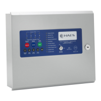
To set Twin Wire mode for zones A-D on the zone extension circuit
boards, move switches A-D on the 4 way DIL switch located on the zone
card to the ‘ON’ position.
Each zone can be independantly set to Twin Wire, switch A relating to
zone A etc.
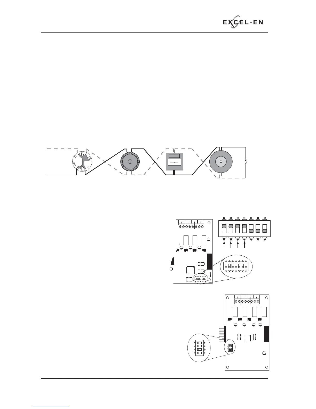
Zone +ve
Zone -ve
+++ +
--- -
4K7 EOL
Resistor
Twin Wire systems require special ‘sav-wire’ detector bases and polarised call points but standard
sounders. Most modern, non addressable, low current, polarised sounders, bells and beacons are
compatible, Cooper Fulleon, Besson, Klaxon etc.
+- +-+- +-
ZONE A ZONE B ZONE C ZONE D
1 2 34
ON
D
C
B
A
TWIN
1 2 34
ON
D
C
B
A
TWIN