Excel-EN Installation, Commissioning & Operating Manual Approved Document Ref: UI-XLEN-01 Issue 7.0
21
SETUP & PROGRAMMING
This setting confi gures the last zone on the panel, (i.e. zone 2 on a 2 zone, zone 4 on a 4 zone, zone 6
on a 6 zone, zone 8 on an 8 zone and zone 12 on a 12 zone), to be used for interconnection from other
control panels.
It is possible, in the Level 3 engineering programming, to setup any zone for this function, however, this is
simply a shortcut method.
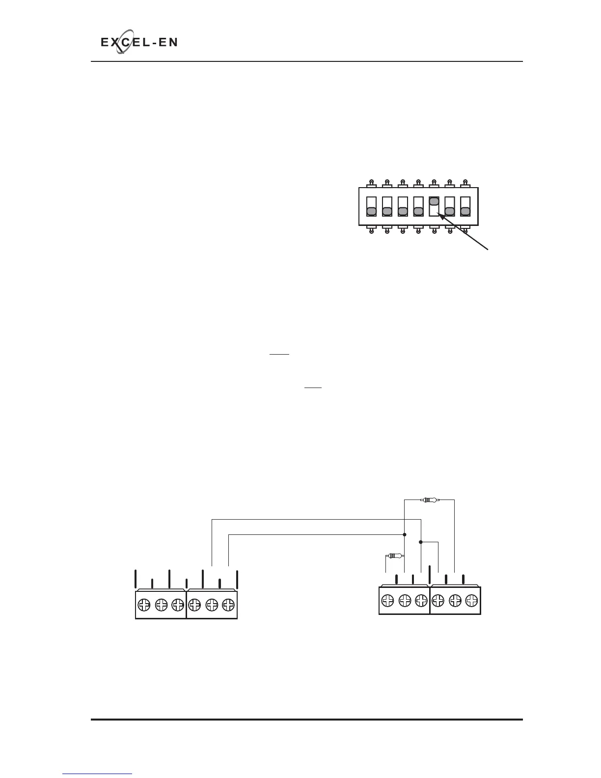
The function is enabled by setting switch 5 on the 7 way DIL
switch located on the main PCB to the ‘ON’ position.
With switch 5 in the ‘ON’ position, the last zone becomes;
Non aux operating.
Note:
If the interface zone is also set to Twin Wire mode and sounders are connected to the zone circuit, the
following sounder operation will apply:
A fi re (470Ω) signal to the interface zone will NOT operate the sounders connected to that Twin Wire circuit.
All other conventional (SNDR1 & SNDR2) and Twin Wire zone sounders will operate as normal.
A fi re (470Ω) signal to any other zone will operate ALL conventional (SNDR1 & SNDR2) and Twin Wire
sounder circuits, including the sounders connected to the interface zone, as normal.
ZONE INTERFACE FUNCTION
1 2 345
67
ON
+-+- +-
ZONE2 ZONE3 ZONE4
CNCNO
NO
CNC
FIRE
FAULT
(optional)
PANEL 1 PANEL 2
470Ω
3K3Ω
Example connection