Excel-EN Installation, Commissioning & Operating Manual Approved Document Ref: UI-XLEN-01 Issue 7.0
55
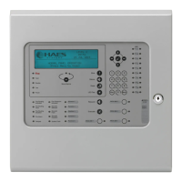
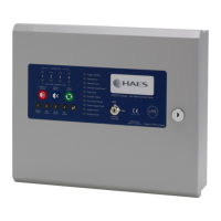
OPERATING
Keypad
RESOUND SILENCE RESET
ENTER
1234
Disable
Mode
Test
Mode
Mute
Buzzer
Test
Lamps
RESOUND (red):
Use to resound the alarms after they have been silenced. Can also be used to invoke full evacuation.
SILENCE (blue):
Use to silence the sounders during an alarm condition.
RESET (green):
Resets the panel back to standby mode.
1: (Disable Mode)
With controls inactive, use to initialise code entry mode for activation of controls. With controls active,
use to disable zones, sounder circuits or aux outputs (see DISABLE MODE section). Also has the
numeric value 1 for code entry.
2: (Test Mode)
With controls inactive, use to initialise code entry mode for activation of controls. With controls active,
use to put zones or sounders circuits into test mode (see TEST MODE section). Also has the numeric
value 2 for code entry.
3: (Mute Buzzer)
Mutes the panels internal fi re and fault buzzer. (The buzzer will still blip every 5-6 seconds during a
fi re or fault condition). This function is operational without the need to activate controls. Also has the
numeric value 3 for code entry.
4: (Test Lamps &
Buzzer)
Use this button to illuminate all LEDs and sound the internal buzzer to check that they are working
correctly. This function is operational without the need to activate controls. Also has the numeric value
4 for code entry.
ENTER:
This button is used to confi rm code entries. It can also be used for fault diagnosis (see FAULT
DIAGNOSIS section).
LED On LED Pulsing
Zones in Fire 1 - 12
N/A Indicates alarm condition in zone.
Zone Fault/Disabled/Test
1 - 12
Indicates zone circuit is disabled or in test
mode.
Indicates a fault in the zone circuit.
Supply Healthy:
Indicates mains and/or battery supply is
present.
N/A
General Fire:
N/A Indicates panel is in alarm condition.
General Fault:
N/A Indicates one or more faults are present.
General Disablement:
Indicates one or more circuits have been
disabled.
Indicates disablement selection mode is
active.
Test Mode:
Indicates one or more circuits are in test
mode
Indicates test mode selection is active.
Sounder Status:
Indicates sounder circuits have been
disabled or are in test mode
Indicates a fault on one or more sounder
circuits.
Aux Output Status:
Indicates auxiliary outputs have been
disabled.
N/A
Power Supply Fault:
N/A Indicates a power supply or battery fault.
System Fault:
Indicates a system failure, panel not
functional or the internal PCB confi guration
has not been set up correctly (see page 26).
Indicates the panel has recovered from a
system fault.
Access Level:
Indicates controls are active (access level 2).
Indicates panel is in confi guration mode
(access level 3).
Repeater Fault:
N/A
Indicates a fault on one or more repeater
panels
Delay Status:
Delays are confi gured Delay is running
Status LED Indicators
Some buttons have other functions within the engineering facilities. These functions are described in the
relevant sections.