TIP:
• All terminal blocks can be unplugged to facilitate wiring.
• The connections to be made are summarised on a label inside the controller cover.
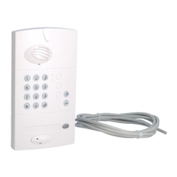
3. Connecting the outdoor caller unit
Connect the 4 outdoor caller unit wires to terminal blocks 15 to 18 on the controller.
4. Connecting an electrical latch
Connect the latch according to the following cable cross-sections:
- in 3 and 4: 0.75 mm
2
up to 15 m/1.5 mm
2
up to 30 m,
- in 5, 6, 7 and 8: 0.22 mm
2
(telephone type wire).
15/Green: Data –
16/Yellow: Data +
17/Red: power +
18/Black: power –
Electrical latch or lock
control (no need for
external power supply)
The position contact feeds back
the latch status to the screen:
- latch closed (contact closed),
- latch open (contact open).
Push-button located on the garden side
for manual latch control. Place this control
device out of reach and sight in relation
to the road (connection not compulsory).
TIP: if the cable between the outdoor caller unit and the controller has
to be lengthened, cut it at a distance of 1 m and then extend the red
and black wires according to the rules below:
- 0.32 mm
2
min. up to 10 m,
- 0.75 mm
2
min. up to 15 m,
- 1.5 mm
2
min. up to 25 m.
Extend the other wires using a telephone type cable and make the
connections via a branch box.
IMPORTANT: for the information feedback to be
properly managed, the position contact (ref. CP500
on the price list) must be wired before power-up
and be in closed position when the radio link is
established between the handset and the controller.
If no contact is connected, the handset display will
show the latch is closed whatever its status.
IMPORTANT: so that the system
recognises the latch, it must be
wired before the radio link is
created between the handset
and the controller.
196
GB