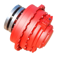
8
When the motor is used fl ange mounted it is normal to use spline. To avoid wear in the splines, the in stal la tion
must be within the specifi ed tolerances in fi g. 4. If it´s possible, let the spline connection be fi l led with oil. If
the spline is not lubricated, there is a risk for wear and corrosion. If there is ra di al and ax i al for ce
Table 2 Dimensions for splines
Dimensions
With splines for fl ange mounting.
0
-0,250
-0,085
-0,150
-0,083
-0,147
0
-0,250
0
-0,220
0
-0,870
0
-1
0
-1
-0,085
-0,150
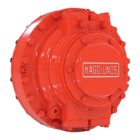
Ta bl e 1 Dimensions for the motor
CA 100
CA 140
CA 210
F
F
A
Fig. 3
Fig. 2
Fig. 3a
CA 50
CA 70
Fig. 4
on the shaft, the spline area in the motor shall be fi l led
with oil. When the mo tor is assembled the splines must
be greased with Molycote Long term 2.
For production of the shaft, see 278 2230, 278 2231, 278
2232, 278 2233, 278 2234, 278 2235, 278 2236, 278
2238 or 278 2239. For control of spline see table 2.
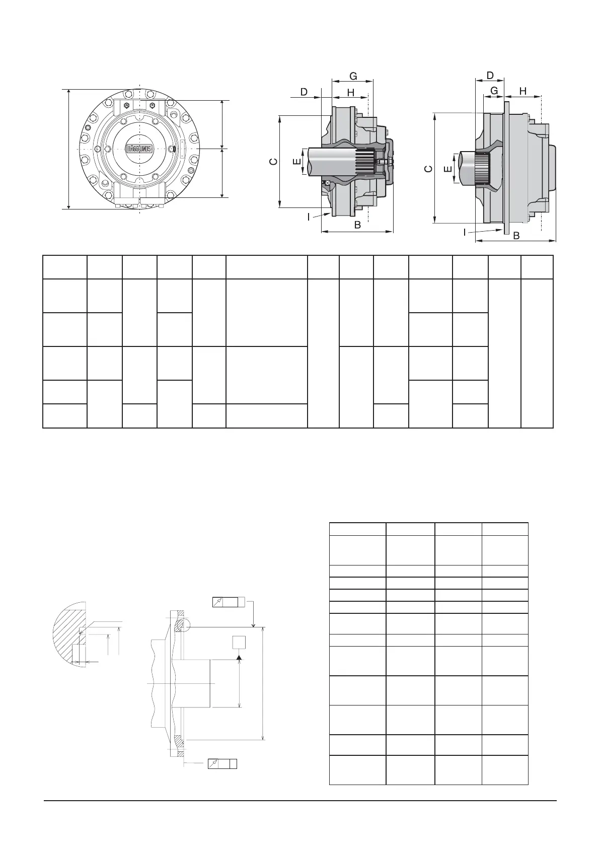
Motor CA50/70 CA100/140 CA210
Toth profi le and
bottom form
DIN 5480 DIN 5480 DIN 5480
Tolerance 8f 8f 8f
Guide Back Back Back
Pressure angle 30° 30° 30°
Module 5 5 5
Number of
teeth
22 26 28
Pitch diameter Ø 110 Ø 130 Ø 140
Minor diameter Ø 109
Ø 129 Ø 139
Major diameter Ø 119 Ø139 Ø 149
Measure over
measuring pins 129,781 149,908 159,961
Diameter of
measuring pins
Ø 10 Ø 10 Ø 10
Addendum
modifi cation
X M
+2,25 +2,25 +2,25
Øi
Ø
Di
Dy
t
R1 (2x)
0,15 A
0,2 A
A
Motor A mm
(in)
B mm
(in)
C mm
(in)
D mm
(in)
E F mm
(in)
G mm
(in)
H mm
(in)
I
Hole Ø
Weight
kg (lb)
Main.
conn.
Drain
conn.
CA 50
464
(18,26)
318,5
(12,54)
390
(15,35) 46,5
(1,83)
N120x5x30x22x9H
188
(7,40)
217,5
(8,56)
160
(6,30)
16xM16
PCD 430
(15,93)
175
(437)
SAE 1
1/4"
BSP
3/4"
CA 70
500
(19,68)
435
(17,12)
20xM16
PCD 470
(18,50)
205
(450)
CA 100
560
(22,05) 406
(15,98)
470
(18,50) 135,5
(5,33) N140x5x30x26x9H
95
(3,74)
158
(6,22)
17xØ22
PCD 520
(20,47)
265
(584)
CA 140
600
(22,62) 510
(20,07)
21xØ22
PCD 560
(22,00)
305
(672)
CA 210
507,5
(19,98)
156
(6,16)
N150x5x30x28x9H 238
(9,37)
395
(870)
 Loading...