16
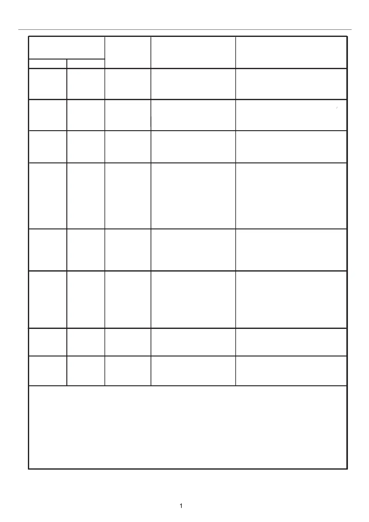
INDOOR UNIT TROUBLE SHOOTING
LED flash times
of indoor PCB
controller
Contents of
Malfunction
Possible reasons
LED4 LED3
0
0
0
1
2
4
Malfunction of indoor
unit ambient temper-
ature sensor
Sensor disconected
,
or brok-
en,or at wrong position,or
short circuit
Malfunction of indoor
unit
piping temper-
ature sensor
EEPROM wrong of
indoor PCB
EEPROM chip disconected
or broken or wrong program-
med,or PCB broken
Abnormal communi-
cation between indo-
or and outdoor units
Wrong connection,or the
wires be disconected or wro-
ng adress setting of indoor
unit or faulty power supply
or faulty PCB or slave unit
malfunction in MAXI system
0
0
0
0
0
7
8
12
13
14
Abnormal communi-
cation between wired
controllee
r and indoor
Wrong connection or wired
controller broken,or PCB
ffaulty
Malfunction of drain
system
Zero cross sigal
wrong
Zero cross sigal detected
wrong
DC Fan motor disconnected
or DC Fan broken or circuit
broken or motor blocked
Sensor disconected
,
or brok-
en,or at wrong position,or
short circuit
Pump motor disconnected
or at wrong position,or the
float swit
,
ch disconnected,
or at wrong position,or the
short circuit bridge disconne
ted
Indoor unit DC fan
motor abnormal
Wired
display
01
02
04
07
07
*flashing
0C
0D
0E
unit
Note:
1.The outdoor failure can also be indicated by thhe indoooor unnit,the checking method as follo-
2.To get much more details about the out door unit failure,please refer to
the outdoor unit
ws:
If the outdoor error code is M(DECIMAL),the indoor unit’s wired controller display will
show the after converted hexadecimal code of “M+20“(
DECIMAL),for example,if the outdoor
error code is 2,the indoor unit wired controller display will flash the error code 16 (2→2+20=22
→change
decimal
22 to
hexadecimal code,get 16)
trouble shooting list.3.For YR-E17,communication error between I.D. PCB and wired
controller, 07 will flash in the main display interface not the check display interface.