Do you have a question about the Haier AH1-070B and is the answer not in the manual?
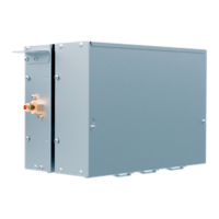
Explains how the AHU valve box connects Haier MRV outdoor units to third-party air handling units.
Details integrated EXV and control parts, flexible installation, and changeable control box location.
Illustrates the configuration of AHU kits with EXV parts, control parts, sensors, and controllers.
Defines the code structure and meaning for valve box models and their specifications.
Lists the parts and functions for AH1-070B, AH1-140B, AH1-280B and AH1-560B, AH1-730B models.
Provides essential safety considerations, warnings, and attention points for proper installation.
Details instructions for installation, including prohibited locations, accessory confirmation, and combinations.
Outlines the steps for installing the connection kit, including pre-installation checks and notices.
Covers connection kit dimensions and lifting dimensions for various models.
Details the process of installing the connection kit, including changing the electrical box direction.
Provides detailed instructions for installing refrigerant pipes, including thermal insulation requirements.
Covers piping maintenance, attention items for connection, and selection of piping dimensions.
Explains pipe connection procedures, insulation methods, and additional refrigerant charging.
Details the installation of temperature sensors (TC1, TC2, room) and provides installation examples and notes.
Covers electrical wiring, including warnings, attention points, and specifications for power and signal lines.
Details the wiring of power and signal lines, including graphical representation and specific connection instructions.
Lists electrical specifications, including power supply, consumption, current, breaker, and cable types.
Explains how to set wired control addresses and connection kit capacity using dip switches SW3_1 to SW3_8.
Details the dip switch settings (SW2) for AH devices address setting and communication center controller address.
Covers code setting for changing control methods, including Plan A (0-10V signal) and Plan B (temperature setting).
Describes Plan C (third-party thermostat) and Plan D (Haier wire controller) for system control.
Details how wired controllers and AHU kit PCB can adjust AHU fan motor speeds based on grades and signal types.
Advises connecting a relay before outputting strong electricity signals to electrical devices.
Illustrates the connection method for a single AHU valve box to an outdoor unit and DDC controller.
Shows how to connect one outdoor unit to multiple AHU valve boxes for systems with a single AHU coil.
Depicts connecting one outdoor unit to multiple AHU valve boxes for systems with multiple AHU coils.
Shows a mixed connection method for multiple outdoor units with one AHU, noting it's not recommended.
Provides a list of error codes (E1, E2, E3, E5-E7, E9) and their corresponding error content for connection kit failures.
Guides on troubleshooting sensor faults, including checking resistance, terminals, and replacing components.
Outlines steps for troubleshooting EEPROM faults in the connection kit, involving power cycling and reconnections.
Provides troubleshooting steps for communication faults between the connection kit and outdoor units, checking wire fixing and circuit integrity.
Details troubleshooting for communication faults between the connection kit and wired controller, including wire checks and controller replacement.
Guides on troubleshooting water drainage faults in the connection kit, focusing on checking CN13 for short circuits.
Explains how to troubleshoot duplicate connection kit addresses by checking and resetting the address with indoor units.
Refers to external documentation for troubleshooting outdoor unit faults.