Do you have a question about the Haier MRV III-RC and is the answer not in the manual?
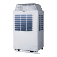
Details the key features of the MRV III-RC system, including operational modes and circuit configurations.
Explains the benefits of the high-efficiency DC inverter scroll compressor, focusing on performance and noise reduction.
Describes the user-friendly design aspects of the outdoor unit, highlighting core technologies and parts.
Discusses the advantages of the large-diameter fan for improved heat exchange efficiency and reduced noise.
Highlights the efficiency improvements and operational benefits of the high-efficiency DC fan motor.
Covers the flexibility in installation and design options, including connectable indoor unit quantities.
Explains the advanced oil separation and return technology for enhanced system reliability and performance.
Details the sub-cooling technology in the heat exchanger to improve unit efficiency and refrigerant flow.
Describes the intelligent defrost control mechanisms for efficient operation in various modes and conditions.
Introduces the valve pipe (VP) system and its role in connecting indoor and outdoor units.
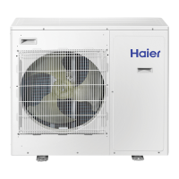
Presents an overview of the available outdoor and indoor units within the product range.
Lists the specifications and models of the outdoor units offered in the product lineup.
Details the various types and models of indoor units available for system configuration.
Provides supplementary information on the lineup of controllers and accessories for the system.
Presents detailed technical specifications for various outdoor unit models, including electrical and mechanical data.
Provides exterior and installation dimensions for different outdoor unit capacities (8-10HP and 12-16HP).
Illustrates the refrigerant piping diagrams for various outdoor unit capacities, showing flow paths.
Presents the electrical wiring diagrams for the outdoor units, detailing component connections.
Defines the operating temperature and humidity ranges for cooling, heating, and combined modes.
Explains the method for calculating cooling capacity using modification coefficients based on operating conditions.
Details the sound pressure levels measured for different outdoor unit groups and operating conditions.
Provides comprehensive guidelines and conditions for the proper installation of outdoor units.
Outlines critical safety precautions and warnings to be strictly followed during outdoor unit installation.
Offers step-by-step instructions for installation, including pre-installation checks and location selection.
Shows the physical dimensions and required clearances for outdoor unit installation.
Details the procedures for installing refrigerant pipes, including connection methods and material selection.
Explains the recommended methods and precautions for connecting refrigerant pipes securely.
Provides dimensions for branch pipes used in 3-pipe systems, based on model and capacity.
Details the dimensions for gather pipes used in connecting multiple outdoor units.
Describes the procedures for confirming system operation after installation, including electrifying and rated operation.
Details the initial checks required after powering on the outdoor unit for the first time.
Explains how to perform rated operation and inspect the outdoor unit's performance under normal conditions.
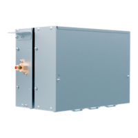
Presents detailed specifications for different valve pipe box models, including capacity and connections.
Provides the external dimensions and mounting details for the valve pipe box.
Shows the electrical wiring diagram for the valve pipe box, detailing terminal connections.
Details the installation process for the valve box, covering parts, functions, and safety.
Lists the components included with the valve box and describes their respective functions.
Covers critical safety considerations and warnings for valve box installation and handling.
Provides instructions for installing the valve box, including location requirements and accessory checks.
Covers electrical wiring requirements, safety precautions, and cable specifications for the valve box.
Shows photos of the outdoor unit and valve box PCBs and explains dip switch settings for configuration.
Explains the identification, definition, and usage of dip switches for outdoor unit configuration.
Provides detailed instructions for setting the BM1 dip switches for various functions like searching and startup.
Explains the functions and settings of the BM2 dip switches for outdoor unit operation modes and selections.
Details the BM3 dip switch settings for selecting outdoor unit type and power supply frequency.
Describes the control logic for the outdoor unit's compressor, fan motor, and other components.
Explains the compressor startup sequence and frequency control based on temperature and pressure.
Details how the compressor operation is controlled based on target high and low pressures.
Describes the fan motor control logic in cooling, heating, and main cooling modes based on pressure.
Explains the conditions for entering and exiting defrosting mode, and the corresponding system actions.
Details the conditions and procedures for the oil return operation to ensure proper lubrication.
Explains the valve box control logic in different operating modes like starting, defrosting, and oil return.
Lists and defines failure codes for indoor and outdoor units, including their indications and descriptions.
Provides troubleshooting flowcharts for various valve box and system failures.
A diagnostic flowchart for troubleshooting valve box EEPROM data errors indicated by LED3.
Troubleshooting flowchart for communication circuit issues between indoor and outdoor units.
Troubleshooting flowchart for diagnosing and resolving high/low pressure sensor failures.
Troubleshooting flowchart for high pressure switch shut-off failures.
Troubleshooting flowchart for addressing issues related to 4-way valve reversing.
Troubleshooting flowchart for communication failures occurring among multiple outdoor units.
Troubleshooting flowchart for communication failures between the inverter module and the control PCB.
Troubleshooting flowchart for diagnosing and resolving DC motor blockages.
Lists sensor codes, their resistance values (KOhm), and corresponding descriptions for system monitoring.
Provides an enthalpy-humidity chart for analyzing air properties and system performance in HVAC applications.
| Model | MRV III-RC |
|---|---|
| Brand | Haier |
| Category | Fan |
| Type | Ceiling Fan |
| Warranty | 2 years |