Do you have a question about the Haier AH1-730B and is the answer not in the manual?
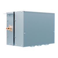
Details capacity, power, dimensions, material, color, weight, and pipe connections for AHU valve box models.
Lists AHU valve box models based on capacity and provides notes on pipe length and connection.
Illustrates the electrical connections and components of the AHU valve box.
Lists the components and functions for AH1-070B, AH1-140B, AH1-280B and AH1-560B, AH1-730B.
Provides crucial safety warnings and precautions for installing the connection kit.
Details critical safety warnings related to installation, electrical hazards, and refrigerant.
Provides guidance on where not to install and general installation considerations.
Confirms accessories, details combination methods and inspection items for AHU valve boxes.
Outlines conditions for selecting the installation location and considerations for noise and wiring.
Explains how to change the electrical box direction and install the connection kit.
Emphasizes electrical safety, proper wiring, and grounding by qualified personnel.
Lists error codes (E1-E9) and their corresponding error contents for connection kit failures.
Provides a flowchart for troubleshooting sensor faults, including replacement steps.
Offers troubleshooting steps for EEPROM faults, including reconnections and PCB replacement.
Flowchart for troubleshooting communication faults between connection kits and outdoor units.
Flowchart for troubleshooting communication faults between connection kits and wired controllers.
| Brand | Haier |
|---|---|
| Model | AH1-730B |
| Number of speeds | 3 |
| Oscillation | Yes |
| Color | White |
| Type | Fan |
| Speed Settings | 3 |