22
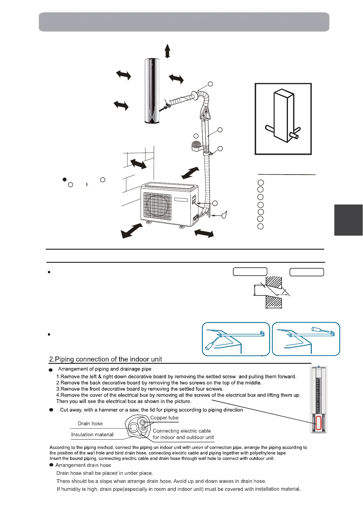
Drawing for the Installation of Indoor and outdoor Unit
Indoor Unit
1.Installation of the indoor machine
F
A
C
E
D
The marks from to
in the
gure are the
parts numbers.
more than 30cm
more than
60cm
more than 60cm
more than
200cm
A
G
G
Back
Left
Front
No barrier in the front
More than 10cm
More than 10cm
Right
Back
Left
Front
Right
Arrangement of piping directions
The models adopt HFC free refrigerant R32
More than 10cm
Optional parts for piping
Non-adhesive tape
Adhesive tape
Saddle (L.S) with screws
Connecting electric cable
for indoor and outdoor
Drain hose
Heating insulating material
Piping hole cover
A
F
C
E
D
G
B
Outdoor side
Thickness
of wall
Wall hole
(Section of wall hole)
Indoor side
Guard
ring
LEFT
BACK
RIGHT
Making a Hole on the Wall and Fitting the Piping Hole Cover
- Positon of the wall hole
Wall hole should be decided according to installation place and piping direction
(refer to installation drawing on the left).
- Making a wall hole
Make a wall hole with a little slope towards outside. Install the guard ring and seal it
with plaster.
- Fixed the indoor machine
The top of the machine is fastened to th
e wall with a metal bracket.
The whole machine is placed horizontally, and the inclination is less than 1°.
Installation of metal bracket
There is no gap between the metal bracket and the machine and
is fastened with screws (Fig. 1). After the machine is placed horizontally,
the metal bracket is connected to the wall by screws(Fig. 2).
Fig. 1
Fig. 2
h
s
i
lg
n
E
 Loading...