Parts and Functions
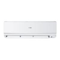
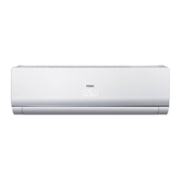
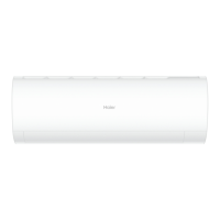
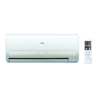
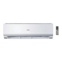
Indoor Unit
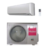
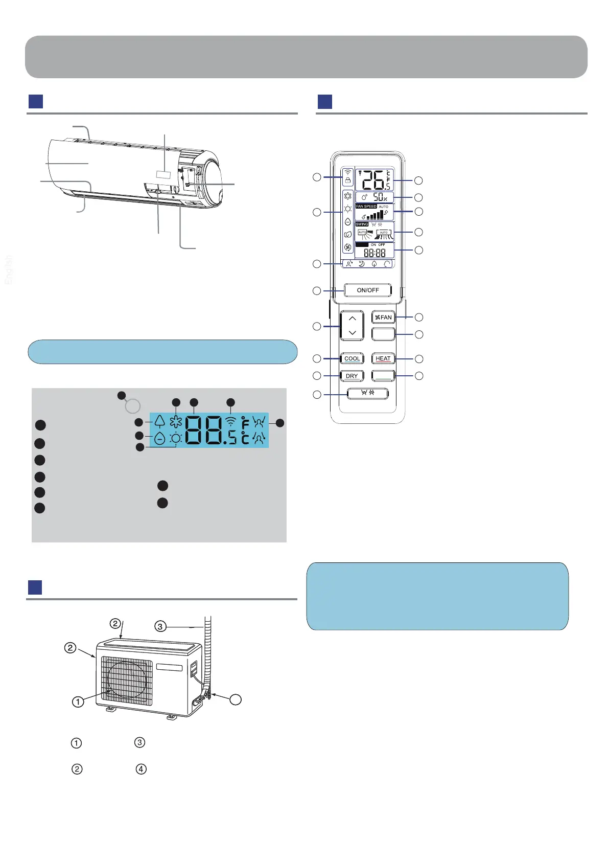
Ou tdoor Unit
Rem ote c ontrol l er
O u t e r s i d e o f t h e c o n t r o l l e r
OUTLET
CONNECTING PIPING
AND ELECTRICAL WIRING
INLET DRAIN HOSE
4
Actual inlet grille may vary from the one shown in the
manual according to the product purchased
1. ECOPILOT button
2. DRY button
3 . COOL button
Used to set COOL operation.
4 .
5.
n.6 oitcnufhcaefoyalpsiD
status
8 . WIFI and CLOCK display
7 . Operation mode display
9 . TEM P display
10 .
Humidity display
11. FAN SPEED display
12. SWING display
Swing up/down display
swing left/right display
14 . FAN button
15. QUIET/TURBO button
16 . HEAT button
17 . SELF CLEAN button
Used to set DRY operation.
13 . TIM ER ON display
TIM ER OFF display
CLOCK display
TIM ER
1
2
3
4
5
6
7
8
9
10
11
12
13
15
16
17
14
TEM P button
used to change setting
temperature
ON / OFF button
Display board
Signal receiver hole
COOL display
HEALTH display
2
6
5
1
4
DRY display
3
WIFI display
7
SENSOR display
8
Ambient temp.display
When receiving the remote
control signal, display the set
temperature.
HEAT display
1
5
2
6
4
8
3
7
ECOPILOT
3
Inlet
Air Purifying Filter
( inside)
ON/OFF
Button
Inlet grille
( adjust left and
ow)
V ertical blade
right air fl
Horizontal flap
( adjust up and down air flow
Don' t adjust it manually)
Outlet
Display board
( inside)
NOTE:
a. Humidity display is unavailable on some models
b. If the model you buy has a WIFI function, press the“ ON/OFF”
button for 5s to emit the WIFI binding signal. Once in the
binding mode, the APP will show how to bind.
S EL F
C L EA N
QUIET/
TURBO
 Loading...