Do you have a question about the Haier AS25RBAHRA-PL and is the answer not in the manual?
Details the model nameplate information and its components.
Provides essential safety warnings and cautions for handling and repair.
Checks for correct embedded wire diameter and grounding.
Highlights critical safety warnings during repair procedures.
Advises on post-repair safety checks and precautions.
Guides on final checks and inspections after completing repairs.
Explains the meaning of various icons used in the manual.
Freezes evaporator with moisture, then melts to remove dirt for clean air.
Control the equipment via Haier hon App on smart devices.
Allows motor to work at higher frequency for rapid cooling.
Provides powerful heating performance in cold winter conditions.
Lowers stand-by power consumption from 8W to 1W.
Provides maximum comfort and energy saving during sleep.
Details system voltage, frequency, and phase requirements.
Provides rated capacity, power consumption, and energy efficiency ratings.
Covers physical dimensions, weight, color, and sound levels.
Specifies the diameter of liquid and gas piping connections.
Details specifications for fan, heat exchanger, air filter, and temperature control.
Lists the types of sensors and their quantity for the unit.
Illustrates the refrigerant flow and components in cooling mode.
Illustrates the refrigerant flow and components in heating mode.
Details pin assignments for PCB connectors and jumper settings.
Diagram showing component layout and connections on the Control PCB.
Table listing unit module, PCB module, and display module information.
Overview of main functions and control specifications for the unit.
Details the automatic operation logic based on temperature.
Specifies temperature control range and airflow speed for cooling.
Details temperature control and wind speed for dehumidifying operation.
Explains heating mode control, fan speed, and cold air proof operation.
Describes activating and using the strength operation mode.
Explains the mute operation for heating and cooling modes.
Details the Nano-Aqua function for air refreshing.
Explains setting 24-hour on/off timing and dormant functions.
Details the 8-hour dormant timing and its effects on fan speed.
Describes the function of the urgency button for automatic mode and test operation.
Protects against indoor heat exchanger frosting by stopping the outdoor system.
Protects the unit by stopping the outdoor system when coil temperature exceeds limits.
Details how the system reports and handles indoor/outdoor operation mismatches.
Explains how malfunction codes are displayed and reset.
Methods for confirming sensor and system abnormalities.
Describes how to operate the indoor system independently of the outdoor unit.
Explains how the system stores its status during power interruptions.
Details the procedure for running the unit's test program.
Describes a function that speeds up the CPU for testing.
Table showing thermistor resistance values at different temperatures.
Provides front, side, and top views with measurements of the indoor unit.
Illustrates the center of gravity points for the indoor unit.
Warnings and procedures for diagnosing unit errors and malfunctions.
Table listing common symptoms and corresponding troubleshooting steps.
Details parameters for key electronic components like the fan motor.
Lists error codes for indoor and outdoor malfunctions and their causes.
Troubleshooting thermistor failures and related abnormalities.
Troubleshooting EEPROM errors and data corruption.
Diagnosing and resolving issues with the indoor DC fan motor.
Diagnosing and resolving issues with the outdoor DC fan motor.
Troubleshooting IPM protection errors and module resistance.
Diagnosing compressor over-current faults and power supply issues.
Troubleshooting communication faults between IPM module and outdoor PCB.
Diagnosing power supply voltage issues affecting the unit.
Troubleshooting overheat protection related to discharge pipe temperature.
Troubleshooting communication faults between indoor and outdoor units.
Troubleshooting compressor position detection circuit faults.
Diagnosing high work-intense protection triggered by heat exchanger temperature.
Schematic diagram of the indoor unit's electronic circuitry.
Schematic diagram of the outdoor unit's electronic circuitry.
Step-by-step guide for removing the front panel of the indoor unit.
Instructions for removing the main casing of the indoor unit.
Procedure for removing the horizontal flap and stepper motor.
Instructions for removing the horizontal louver and control box.
Steps for removing the heat exchanger from the indoor unit.
Procedure for removing the fan rotor and fan motor.
| Refrigerant | R32 |
|---|---|
| Power Supply | 220-240V, 50Hz |
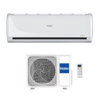
| Type | Split System |
| Cooling Capacity | 2.6 kW |
| Heating Capacity | 2.6 kW |