Do you have a question about the Haier AU362XHERA and is the answer not in the manual?
Details for the 4-way cassette indoor unit installation and operation.
Information on installing and operating the convertible indoor unit.
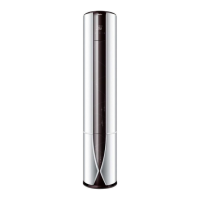
Installation and operational guidance for the console indoor unit.
Installation and operational guidance for the duct indoor unit.
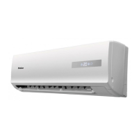
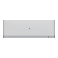
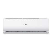
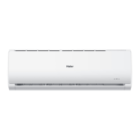
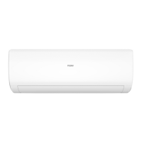
Installation and operational guidance for the wall-mounted indoor unit.
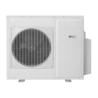
Details regarding the outdoor unit, its specifications, and installation.
Overview of the X Multi series product range and models available.
Specifies the operating temperature limits for cooling and heating modes.
Details on self-diagnosis, central control, and temperature compensation features.
Technical specifications for the AU182XFERA model, including performance and dimensions.
Technical specifications for the AU222XFERA model, including performance and dimensions.
Technical specifications for the AU252XGERA model, including performance and dimensions.
Technical specifications for the AU282XHERA model, including performance and dimensions.
Technical specifications for the AU342XHERA model, including performance and dimensions.
Technical specifications for the AU362XHERA model, including performance and dimensions.
Technical specifications for AS series models including performance and dimensions.
Technical specifications for AB series models including performance and dimensions.
Technical specifications for AC series models including performance and dimensions.
Technical specifications for AF series models including performance and dimensions.
Visual representations and measurements for various outdoor unit models.
Visual representations and measurements for cassette and convertible indoor units.
Visual representations and measurements for ceiling concealed indoor units.
Visual representations and measurements for console and wall mounted indoor units.
Data tables detailing various combinations of indoor and outdoor units and their performance.
Wiring diagram specific to the AU182XFERA model for system connections.
Wiring diagram specific to the AU252XGERA model for system connections.
Wiring diagram specific to the AU362XHERA model for system connections.
Specifies piping length and drop limitations for AU182XFERA and AU222XFERA models.
Specifies piping length and drop limitations for AU28-342XHERA models.
Specifies piping length and drop limitations for AU362XHERA models.
Details on selecting, connecting, and insulating refrigerant pipes.
Step-by-step guide for vacuumizing the system using a vacuum pump.
Instructions on proper electric wiring methods and terminal connections.
Methods for connecting wires to terminals and securing cables.
Detailed instructions for wiring the indoor unit's electrical components.
Further details on indoor unit wiring, including cable types and warnings.
Steps to set communication addresses using the remote controller.
Steps to set communication addresses using DIP switches SW01 and SW03.
Detailed procedures for connecting wires using ring terminals, straight terminals, and crimp connections.
Information on pipe expansion dimensions and correct tightening torques.
Details on pipe types, insulation, hose, and drain pipe specifications.
Guidance on installing hoses and confirming drain functionality.
Guidelines for adding refrigerant and requirements for pipe cutting/expansion.
Illustrates the correct installation procedure for indoor and outdoor units.
Procedures for flaring pipes and bending them correctly for outdoor unit connections.
Checklist of tasks to be completed before starting test running.
Items to check during test run for both indoor and outdoor units.
Guidance for customers on unit operation and manual delivery.
Instructions for mounting the cover plate and intake grill.
Lists tools and accessories needed for cassette type installation.
Criteria for choosing the optimal installation location for cassette units.
Guidelines for determining the best mounting position for convertible units.
Instructions for drilling holes and connecting the drain hose for floor console units.
Steps for drilling and installing anchor bolts for under-ceiling units.
Instructions for installing mounting brackets and securing the indoor unit.
Lists tools and accessories for duct type units.
Criteria for selecting the optimal installation location for duct type units.
Step-by-step guide for installing duct type indoor units.
Specifics on installing air discharge and return ducts for duct type units.
Procedures for insulating air ducts and installing suspension screws.
Visual identification of components on the outdoor unit's PCB.
Electrical wiring schematic for AU182XFERA and AU222XFERA outdoor units.
Electrical wiring schematic for AU252XGERA outdoor unit.
Electrical wiring schematic for AU282XHERA and AU342XHERA outdoor units.
Electrical wiring schematic for AU362XHERA outdoor unit.
Explanation of DIP switch settings and their functions on the outdoor unit.
Visual identification of components on the AB and AD indoor unit PCBs.
Electrical wiring schematic for AB and AD indoor units.
Electrical wiring schematic for AD***XLERA indoor units.
Visual identification of components on the AC142-182XCERA indoor unit PCB.
Electrical wiring schematic for AC142-182XCERA indoor units.
Detailed definitions of DIP switch functions for cassette and convertible indoor units.
Definitions of sensor signals and explanations of Dry, Fan, and Auto operation modes.
Handling of abnormal operations, discontinuous operation, and anti-cold air control.
Control mechanisms for indoor fan motor during defrosting and swing motor operations.
Procedures for blowing remaining heat and handling unit shut-off.
Functions related to water pump, compulsory defrosting, and trial operation modes.
Functions for timer, sleep mode, and setting indoor unit addresses.
Features like negative ion, auto-restart, and passive contact control for indoor units.
Methods for setting temperature compensation and understanding protection mechanisms.
Visual identification of components on the AF092-122XCERA indoor unit PCB.
Electrical wiring schematic for AF092-122XCERA indoor units.
Detailed definitions of DIP switch functions for console type indoor units.
Visual identification of components on the AS***XVERA indoor unit PCB.
Electrical wiring schematic for AS***XVERA indoor units.
Electrical wiring schematic for AS182XVERA indoor units.
Detailed definitions of SW01 and SW02 DIP switch functions for wall mounted units.
Explanation of cooling, heating, dry, fan, auto modes, and abnormal operations.
Covers remaining heat, anti-freeze, overload, timer, sleep, and unit numbering.
Lists failure codes and possible reasons for AU18,22,28,342XHERA models.
Lists failure codes and possible reasons for AB*XCERA and AC*XCERA models.
Lists failure codes and possible reasons for AD*XLERA models.
Lists failure codes and possible reasons for AD*XCERA models.
Lists failure codes and possible reasons for AF*XCERA models.
Lists failure codes and possible reasons for AS*XVERA models.
Diagnostic steps for issues with the operation panel display.
Diagnostic steps for sensor-related failures.
Steps for diagnosing communication issues and PCB faults.
Diagnostic steps for repeated unit numbers and indoor fan motor failures.
Guidance for diagnosing issues indicated by the outdoor unit's failure code.
Diagnostic steps for outdoor unit sensor failures and over current protection.
Diagnostic steps for high-pressure protection faults.
Diagnostic steps for low-pressure switch failures.
Performance curves showing cooling capacity vs. outdoor temperature for AU182XFERA.
Performance curves showing heating capacity vs. outdoor temperature for AU182XFERA.
Performance curves showing cooling capacity vs. outdoor temperature for AU222XFERA.
Performance curves showing heating capacity vs. outdoor temperature for AU222XFERA.
Performance curves showing cooling capacity vs. outdoor temperature for AU252XGERA.
Performance curves showing heating capacity vs. outdoor temperature for AU252XGERA.
Performance curves showing cooling capacity vs. outdoor temperature for AU282XHERA.
Performance curves showing heating capacity vs. outdoor temperature for AU282XHERA.
Performance curves showing cooling capacity vs. outdoor temperature for AU342XHERA.
Performance curves showing heating capacity vs. outdoor temperature for AU342XHERA.
Performance curves showing cooling capacity vs. outdoor temperature for AU362XHERA.
Performance curves showing heating capacity vs. outdoor temperature for AU362XHERA.
Air velocity distribution patterns for AB092-182XCERA during cooling operation.
Temperature distribution patterns for AB092-182XCERA during cooling operation.
Air velocity distribution patterns for AB092-182XCERA during heating operation.
Temperature distribution patterns for AB092-182XCERA during heating operation.
Air velocity distribution patterns for AC14/182XCERA during cooling operation.
Temperature distribution patterns for AC14/182XCERA during cooling operation.
Air velocity distribution patterns for AC14/182XCERA during heating operation.
Temperature distribution patterns for AC14/182XCERA during heating operation.
Air velocity distribution patterns for ceiling units during cooling operation.
Temperature distribution patterns for ceiling units during cooling operation.
Air velocity distribution patterns for ceiling units during heating operation.
Temperature distribution patterns for ceiling units during heating operation.
Air velocity distribution patterns for AF09/122XCERA during cooling operation.
Temperature distribution patterns for AF09/122XCERA during cooling operation.
Air velocity distribution patterns for AF09/122XCERA during heating operation.
Temperature distribution patterns for AF09/122XCERA during heating operation.
Air velocity distribution patterns for wall mounted units under fan-only operation.
Charts showing air flow rates at different static pressures for AD092/AD122XLERA models.
Charts showing air flow rates at different static pressures for AD142/AD182XLERA models.