FQG-B180(GAS)
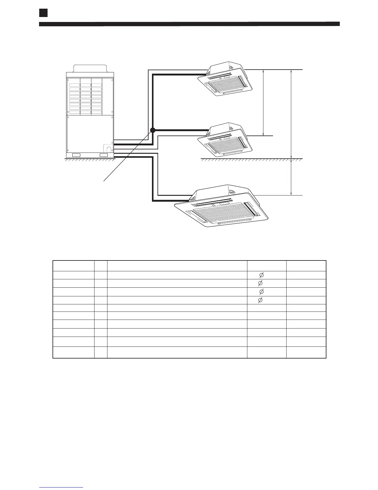
L1
L2
L3
h H +
H -
A1
A2
B1
Descriptions
Recommended
A1/A2 liquid pipe
A1/A2 Gas pipe
B1 Liquid pipe
mm
Item
The piping length information, please refer the following table.
Maximum
Unit
B1 Gas pipe
L1 (one way)
L2 (one way)
L3 (one way)
h
H +
H -
mm
mm
mm
m
m
m
m
m
m
Size of the liquid side connection pipe
Pipe length when the compressor connects with two indoor units
Drop between the two indoor units those in the same system
Drop between the outdoor unit and the indoor unit
*15
*5
*10
*10
/
/
/
/
Size of the gas side connection pipe
Size of the liquid side connection pipe
Size of the gas side connection pipe
Pipe length when the compressor connects with two indoor units
Pipe length when the compressor connects only one indoor unit
Drop between the outdoor unit and the indoor unit
9.52
9.52
15.88
19.05
*15
*30
*25
*5
*20
*30
*25
*50
2. Limitations on the piping work (Take a trio combination as an example)
Installation diagrams