Do you have a question about the Haier AU96NFTAHA and is the answer not in the manual?
Provides fundamental information and examples of MRV system configurations and components.
Step-by-step installation guide for convertible type indoor units.
Installation procedures for cassette units featuring four-directional airflow.
Installation methods for air duct units designed for high static pressure applications.
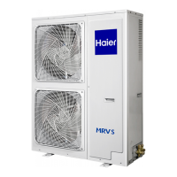
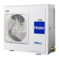
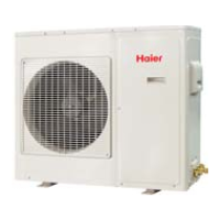
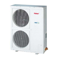
Installation guidelines and dimensions for the outdoor unit.
Specifications for the dimensions of Y-type and Comb-shape manifold pipes.
Detailed wiring schematics for various types of indoor units.
Electrical connection diagrams for AU96NFTAHA and AU55NFUAHA outdoor units.
Illustrates the overall refrigerant piping system for different outdoor units.
Specifies the maximum allowable lengths and height differences for refrigerant pipes.
Methodology for selecting appropriate refrigerant pipe dimensions based on capacity and length.
Calculations for supplementary refrigerant injection based on pipe length and diameter.
Explains the calculation methods for refrigerating and heating capacities using various factors.
Provides formulas and charts for calculating heating capacity based on operating conditions.
Discusses capacity adjustments related to frosting conditions during heating operations.
Method for determining the operational capacity of a single indoor unit within a system.
Graphical representation of power consumption versus capacity for different operating conditions.
Covers automatic settings, running modes, and temperature compensation for indoor units.
Explains the control logic and functions of the outdoor unit.
Procedure for automatic address setting and potential issues during this process.
Troubleshooting inspection code '95' related to power supply and communication faults.
Steps to verify correct refrigerant pipe and signal line connections for system control.
How the outdoor unit controls the ON/OFF functions of connected indoor units.
Methods for eliminating system abnormalities using remote controllers or outdoor unit PCBs.
Procedure to judge the functionality of the remote controller through the outdoor unit.
Steps to confirm the proper functioning of the connected outdoor unit via the remote controller.
Outlines the systematic procedure for conducting the trial run.
Checklists for confirming installation and system readiness prior to trial run.
Detailed steps for confirming system operation after the trial run is completed.
General methods for inspecting components and identifying potential issues.
Flowcharts for systematically judging faults based on observed symptoms.
Specific methods for diagnosing faults indicated on the remote controller display.
Resistance vs. temperature data for various temperature sensors used in the system.
Tables and graphs showing the output voltage characteristics of pressure sensors.
Data table for outdoor unit control functions based on SW01/SW02 settings.
Data table for outdoor unit control functions, including sensor and compressor status.
Data table for outdoor unit control functions, focusing on operational modes and requirements.
Meaning of 'standby' display and conditions causing it.
Meaning of 'preheat defrost' display and conditions causing it.
Backup running procedures for indoor units when sensors detect faults.
Backup running procedures for outdoor units based on sensor data and manual settings.
Backup running for inverter systems, noting 6HP unit limitations.
Backup running procedures for commercial compressors when faults occur.
Backup running procedure when the Pd sensor detects a fault.
Backup running procedure when the Ps sensor detects a fault.
Backup running procedure when the TS sensor detects a fault.
Backup running procedure when the TE sensor detects a fault.
Disassembly procedures for the indoor unit, categorized by component type.
| Brand | Haier |
|---|---|
| Model | AU96NFTAHA |
| Category | Air Conditioner |
| Language | English |