17
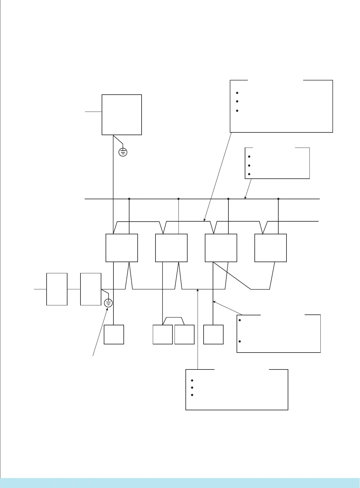
2. Wiring diagram of outdoor unit
a. Wiring connection diagram
Outdoor unit
L1
L2
L3
N
P
Q
3N, 380V
Earth point for indoor and outdoor
communication link shielding layer.
The shielding layers in other positions
should be connected each other, and
the shielding layers in the end shouldconduct insulation treatment, so as toensure single point earting of the
shielding layer.
Indoor and outdoor
communication link.
Two-core cable, no polarity.
Shielded wire.
Wire thickness: 1.5 mm
2
, below 500 m.
Indoor power cord.
Three-core cable.
Wire thickness
2.00 mm2.
Earthing wire 2.00 mm
2
.
Indoor unit 1
PQ
ABC XY
Indoor unit 2
ABC XY
Indoor unit 3
(master)
ABC XY
Indoor unit 4
(slave)
BC
Power
supply
unit
A X
B Y
ABC
Remote
controller
Remote
controller
(master)
Remote
controller
(slave)
Remote
controller
Remote
controller
Remote controller. Three-core, with
polarity (for salve indoor unit, two-
core cable should be adopted)
Wire
thickness
: 0.75 mm2; below
500 mm
Earth point for centralized control communication
link shielding layer. The shielding layers in other
positions should be connected each other, and the
shielding layers in the end should conduct insulation
treatment, so as to ensure single point earting of the
shielding layer.
Centralized control
communication link.
Two-core cable, no polarity.
Shielded wire.
Wire
thickness
: 1.5 mm2, below 500 m.2.0 mm2, below 1000 m.
1N, 220V
1N, 220V
Central controller
PQ
PQ PQ
Все каталоги и инструкции здесь: http://splitoff.ru/tehn-doc.html
 Loading...