Do you have a question about the Haier AV08NMSETA and is the answer not in the manual?
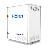
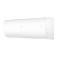
Lists various types of indoor units available for the MRV S'' system.
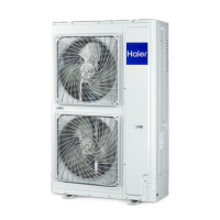
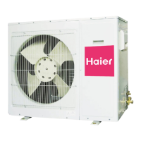
Details key features of the outdoor unit, including design and technology.
Shows how temperature, airflow, and pipe length affect system capacity.
Essential safety precautions and general guidelines for outdoor unit installation.
Lists R410A tools and criteria for selecting an installation location.
Procedures for safely moving and lifting the outdoor unit.
Required clearances for installation and maintenance access.
Illustrates communication wiring methods for indoor and outdoor units.
Shows power wiring configurations for outdoor and indoor units.
Covers delay functions, operation modes, and conditions for trial operation.
Step-by-step guide for conducting trial operation.
Inspection and confirmation steps before starting trial operation.
Steps to confirm proper operation in cooling and heating modes.
Diagnostic flowcharts for electrical and operational issues during trial operation.
Image of the outdoor PCB with key components labeled.
Explanation of the BM1 dip switch settings and their functions.
Explanation of the BM2 dip switch settings and their functions.
Details the parameters displayed by the digital tube and their selection.
Lists failure codes related to sensors and communication.
Lists failure codes for pressure sensors and compressor protection.
Lists failure codes for compressor, DC motor, and refrigerant issues.
Lists failure codes for power modules, transducers, and communication.
Diagnosing temperature and oil sensor failures.
Troubleshooting communication issues between indoor and outdoor units.
Diagnosing high/low pressure sensor and EEPROM failures.
Resolving high pressure switch and discharge temperature protection issues.
Diagnosing 4-way valve and compression ratio issues.
Troubleshooting power module overcurrent and overload protection.
Provides resistance values for various temperature sensors at different temperatures.
Graphical representation of air properties for system analysis.
| Brand | Haier |
|---|---|
| Model | AV08NMSETA |
| Category | Air Conditioner |
| Language | English |