SERVICE MANUAL
Model:
42
Issue
Rev.
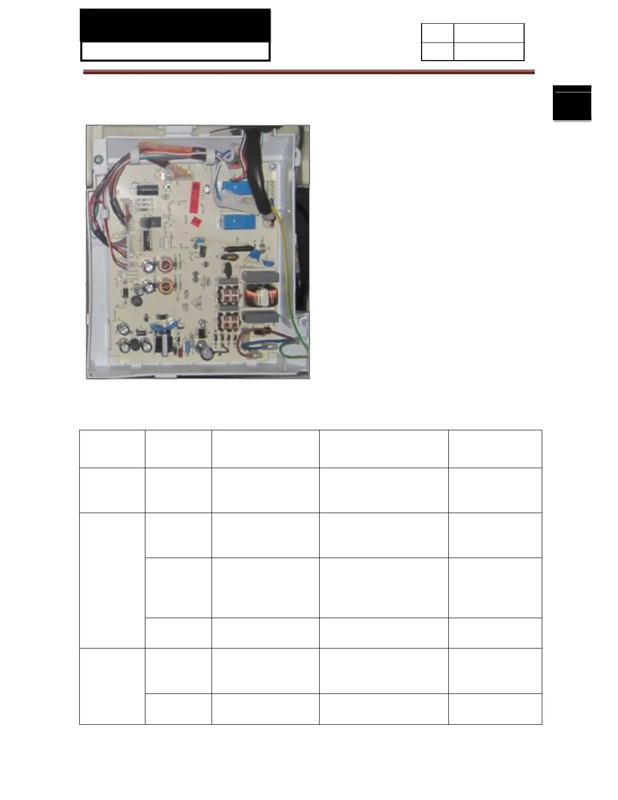
9-2-2. PCB photo
9-2-3. PCB connection technical data
Connector
NO.
Connection Testing part Testing part location Normal data
CN1
1.NULL
2.NULL
3.NULL
/ / /
CN2
1.Black
2.Orange
3. Brown
Evaporating Fan
motor
The inside of the air duct of
the freezer
Working volt
8V-13V
4.White
5.Blue
6.Yellow
7. Red
Damper motor The inside of the air duct of
the chiller chamber
Working volt 12V
8.Purple
9. Green
Refrigerating LED The top of the refrigerating
chamber
Working volt 12V,
power 2W
CN3
1.Pink
2.Black
3. Grey
Switch of the
refrigerating chamber
door
The door body of the
refrigerating chamber
Working volt 5V
4.Grey
5. Black
Frequency signal wire Connect to the frequency
conversion board
Working volt 5V
 Loading...